Page 55 of 198

3-5
PRE-OPERATION INSPECTION AND MAINTENANCE
PRE-OPERATION INSPECTION AND MAINTENANCE
Before riding for break-in operation, practice or a race, make sure the machine is in good operating condition.
Before using this machine, check the following points.
GENERAL INSPECTION AND MAINTENANCE
Item Routine Page
CoolantCheck that coolant is filled up to the radiator cap. Check the cool-
ing system for leakage.P.3-6 – 7
FuelCheck that a fresh gasoline is filled in the fuel tank. Check the fuel
line for leakage.P.1-13
Engine oilCheck that the oil level is correct. Check the crankcase and oil line
for leakage.P.3-9 – 10
Gear shifter and clutchCheck that gears can be shifted correctly in order and that the
clutch operates smoothly.P.3-7
Throttle grip/HousingCheck that the throttle grip operation and free play are correctly
adjusted. Lubricate the throttle grip and housing, if necessary.P.3-7 – 8
Brakes Check the play of front brake and effect of front and rear brake. P.3-14 – 16
Drive chainCheck drive chain slack and alignment. Check that the drive chain
is lubricated properly.P.3-17 – 18
WheelsCheck for excessive wear and tire pressure. Check for loose
spokes and have no excessive play.P.3-20 – 21
SteeringCheck that the handlebar can be turned smoothly and have no ex-
cessive play.P.3-21 – 22
Front forks and rear shock
absorberCheck that they operate smoothly and there is no oil leakage.
P.3-18 – 20
Cables (wires)Check that the clutch and throttle cables move smoothly. Check
that they are not caught when the handlebars are turned or when
the front forks travel up and down.—
Exhaust pipe Check that the exhaust pipe is tightly mounted and has no cracks. P.4-3 – 6
Rear wheel sprocket Check that the rear wheel sprocket tightening bolt is not loose. P.3-17
Lubrication Check for smooth operation. Lubricate if necessary. P.3-23
Bolts and nuts Check the chassis and engine for loose bolts and nuts. P.1-15
Lead connectorsCheck that the CDI magneto, CDI unit, and ignition coil are con-
nected tightly.P.1-7
SettingsIs the machine set suitably for the condition of the racing course
and weather or by taking into account the results of test runs be-
fore racing? Are inspection and maintenance completely done?P.7-1 – 10
Page 67 of 198

3-17
CHASSIS
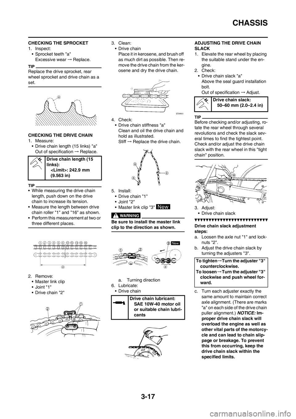
CHECKING THE SPROCKET
1. Inspect:
• Sprocket teeth "a"
Excessive wear→Replace.
Replace the drive sprocket, rear
wheel sprocket and drive chain as a
set.
CHECKING THE DRIVE CHAIN
1. Measure:
• Drive chain length (15 links) "a"
Out of specification→Replace.
• While measuring the drive chain
length, push down on the drive
chain to increase its tension.
• Measure the length between drive
chain roller "1" and "16" as shown.
• Perform this measurement at two or
three different places.
2. Remove:
• Master link clip
•Joint "1"
• Drive chain "2"3. Clean:
• Drive chain
Place it in kerosene, and brush off
as much dirt as possible. Then re-
move the drive chain from the ker-
osene and dry the drive chain.
4. Check:
• Drive chain stiffness "a"
Clean and oil the drive chain and
hold as illustrated.
Stiff→Replace the drive chain.
5. Install:
• Drive chain "1"
•Joint "2"
• Master link clip "3"
Be sure to install the master link
clip to the direction as shown.
a. Turning direction
6. Lubricate:
• Drive chainADJUSTING THE DRIVE CHAIN
SLACK
1. Elevate the rear wheel by placing
the suitable stand under the en-
gine.
2. Check:
• Drive chain slack "a"
Above the seal guard installation
bolt.
Out of specification→Adjust.
Before checking and/or adjusting, ro-
tate the rear wheel through several
revolutions and check the slack sev-
eral times to find the tightest point.
Check and/or adjust the drive chain
slack with the rear wheel in this "tight
chain" position.
3. Adjust:
• Drive chain slack
Drive chain slack adjustment
steps:
a. Loosen the axle nut "1" and lock-
nuts "2".
b. Adjust the drive chain slack by
turning the adjusters "3".
c. Turn each adjuster exactly the
same amount to maintain correct
axle alignment. (There are marks
"a" on each side of the drive chain
puller alignment.) NOTICE: Im-
proper drive chain slack will
overload the engine as well as
other vital parts of the motorcy-
cle and can lead to chain slip-
page or breakage. To prevent
this from occurring, keep the
drive chain slack within the
specified limits. Drive chain length (15
links):
: 242.9 mm
(9.563 in)
Drive chain lubricant:
SAE 10W-40 motor oil
or suitable chain lubri-
cants
Drive chain slack:
50–60 mm (2.0–2.4 in)
To tighten→Turn the adjuster "3"
counterclockwise.
To loosen→Turn the adjuster "3"
clockwise and push wheel for-
ward.
Page 123 of 198

4-49
KICK SHAFT AND SHIFT SHAFT
INSTALLING THE STOPPER
LEVER
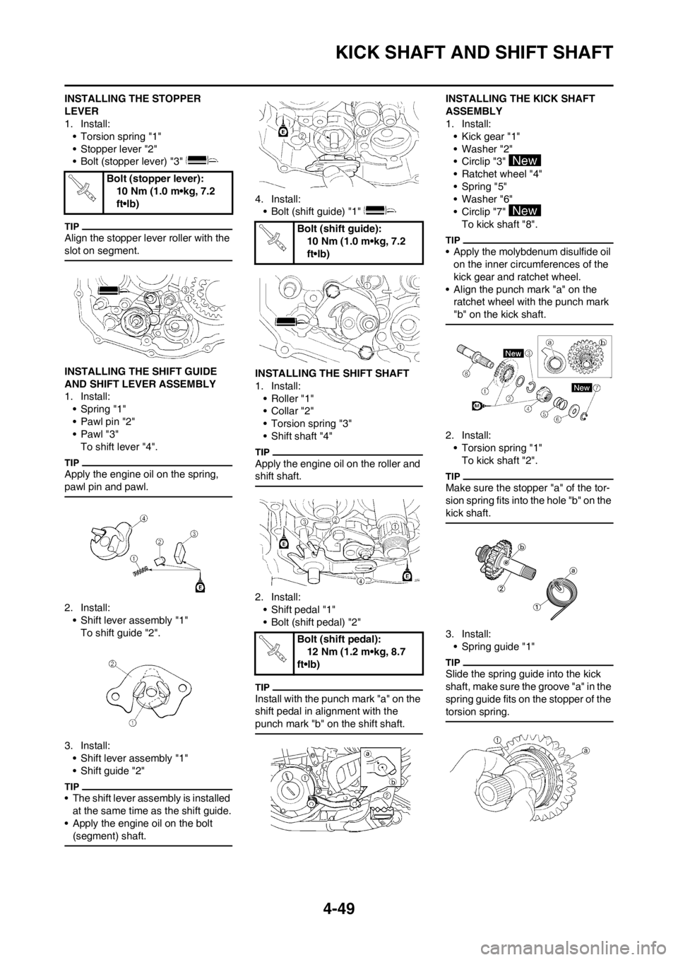
1. Install:
• Torsion spring "1"
• Stopper lever "2"
• Bolt (stopper lever) "3"
Align the stopper lever roller with the
slot on segment.
INSTALLING THE SHIFT GUIDE
AND SHIFT LEVER ASSEMBLY
1. Install:
• Spring "1"
• Pawl pin "2"
•Pawl "3"
To shift lever "4".
Apply the engine oil on the spring,
pawl pin and pawl.
2. Install:
• Shift lever assembly "1"
To shift guide "2".
3. Install:
• Shift lever assembly "1"
• Shift guide "2"
• The shift lever assembly is installed
at the same time as the shift guide.
• Apply the engine oil on the bolt
(segment) shaft.
4. Install:
• Bolt (shift guide) "1"
INSTALLING THE SHIFT SHAFT
1. Install:
• Roller "1"
• Collar "2"
• Torsion spring "3"
• Shift shaft "4"
Apply the engine oil on the roller and
shift shaft.
2. Install:
• Shift pedal "1"
• Bolt (shift pedal) "2"
Install with the punch mark "a" on the
shift pedal in alignment with the
punch mark "b" on the shift shaft.
INSTALLING THE KICK SHAFT
ASSEMBLY
1. Install:
• Kick gear "1"
• Washer "2"
• Circlip "3"
• Ratchet wheel "4"
• Spring "5"
• Washer "6"
• Circlip "7"
To kick shaft "8".
• Apply the molybdenum disulfide oil
on the inner circumferences of the
kick gear and ratchet wheel.
• Align the punch mark "a" on the
ratchet wheel with the punch mark
"b" on the kick shaft.
2. Install:
• Torsion spring "1"
To kick shaft "2".
Make sure the stopper "a" of the tor-
sion spring fits into the hole "b" on the
kick shaft.
3. Install:
• Spring guide "1"
Slide the spring guide into the kick
shaft, make sure the groove "a" in the
spring guide fits on the stopper of the
torsion spring.
Bolt (stopper lever):
10 Nm (1.0 m•kg, 7.2
ft•lb)
Bolt (shift guide):
10 Nm (1.0 m•kg, 7.2
ft•lb)
Bolt (shift pedal):
12 Nm (1.2 m•kg, 8.7
ft•lb)