Page 41 of 152
4-16
4
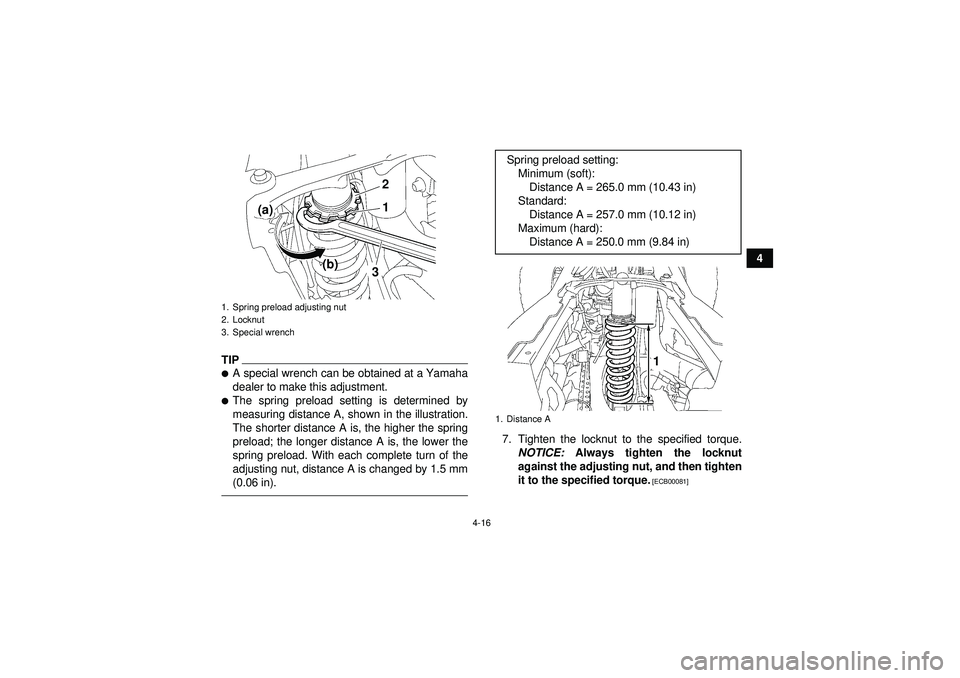
TIP�A special wrench can be obtained at a Yamaha
dealer to make this adjustment.�The spring preload setting is determined by
measuring distance A, shown in the illustration.
The shorter distance A is, the higher the spring
preload; the longer distance A is, the lower the
spring preload. With each complete turn of the
adjusting nut, distance A is changed by 1.5 mm
(0.06 in).
7. Tighten the locknut to the specified torque.NOTICE: Always tighten the locknut
against the adjusting nut, and then tighten
it to the specified torque.
[ECB00081]
1. Spring preload adjusting nut
2. Locknut
3. Special wrench
2
1
(a)
(b)3
Spring preload setting:
Minimum (soft):Distance A = 265.0 mm (10.43 in)
Standard: Distance A = 257.0 mm (10.12 in)
Maximum (hard): Distance A = 250.0 mm (9.84 in)1. Distance A
1
U1PD60E0.book Page 16 Monday, June 13, 2011 2:57 PM
Page 42 of 152

4-17
48. Place the air filter case in the original position,
connect the air intake duct, and then tighten
the clamp screw at the carburetor side.
NOTICE: Make sure that the air intake duct
is properly connected to the carburetor,
and that the clamp screw is tightened se-
curely.
[ECB01170]
9. Install the bolts, install the hose joint, and then connect the hoses.
10. Install the seat.
WARNING
EWB00450This shock absorber assembly contains highly
pressurized nitrogen gas. If the shock absorb-
er assembly is damaged, it could explode
causing injury or property damage. Shock ab-
sorber cylinder damage could also result in
poor handling which could cause an accident.�Do not tamper with or attempt to open the
cylinder assembly.�Do not subject the shock absorber assembly
to an open flame or other high heat.
�Do not deform or damage the cylinder in any
way.�Do not dispose of a damaged or worn out
shock absorber assembly yourself. Take the
shock absorber assembly to a Yamaha deal-
er for any service.
Tightening torque: Locknut:44 Nm (4.4 m ·kgf, 32 ft· lbf)
U1PD60E0.book Page 17 Monday, June 13, 2011 2:57 PM
Page 82 of 152
8-2
8
EBU27111Owner’s manual and tool kit Be sure to put this owner ’s manual in the plastic
bag and to always carry it as well as the owner ’s
tool kit and the low-pressure tire gauge in their re-
spective compartments under the seat.
The service information included in this manual
and the tools provided in the owner ’s tool kit are in-
tended to assist you in the performance of preven-
tive maintenance and minor repairs. However, additional tools such as a torque wrench may be
necessary to perform certain maintenance work
correctly.
TIPIf you do not have the tools or experience required
for a particular job, have a Yamaha dealer perform
it for you.
1. Low-pressure tire gauge
2. Owner
’s tool kit
3. Owner ’s manual
3
2
1
U1PD60E0.book Page 2 Monday, June 13, 2011 2:57 PM
Page 94 of 152

8-14
8To install the spark plug
1. Clean the surface of the spark plug gasket and its mating surface, and then wipe off any
grime from the spark plug threads.
2. Install the spark plug with the spark plug wrench, and then tighten it to the specified
torque.
TIPIf a torque wrench is not available when installing
the spark plug, a good estimate of the correct
torque is 1/4 –1/2 turn past finger tight. However,
the spark plug should be tightened to the specified
torque as soon as possible.3. Install the spark plug cap.
4. Place the fuel tank in the original position, and then install the bolt.
5. Remove the fuel tank cap by turning it coun- terclockwise.
6. Place the panel in the original position. 7. Install the fuel tank cap by turning it clockwise.
8. Install the bolts and the quick fastener screws.
9. Install the seat.
EBU23307Engine oil and oil filter element The engine oil level should be checked before
each ride. In addition, the oil must be changed and
the oil filter element replaced at the intervals spec-
ified in the periodic maintenance and lubrication
chart.
Tightening torque:
Spark plug:13 Nm (1.3 m ·kgf, 9.4 ft ·lbf)1. Projection
2. Slot
2 1
U1PD60E0.book Page 14 Monday, June 13, 2011 2:57 PM
Page 98 of 152
8-18
89. Check the O-rings for damage, and replace
them if necessary. 10. Install a new oil filter element and new O-
rings.
TIPMake sure that the O-rings are properly seated.11. Install the oil filter element cover by installingthe bolts, and then tighten them to the speci-
fied torque.
1. Oil filter element cover
2. Bolt
1
2
1. Oil filter element
2. O-ringTightening torque:
Oil filter element cover bolt:10 Nm (1.0 m ·kgf, 7.2 ft ·lbf)
1
2
2
U1PD60E0.book Page 18 Monday, June 13, 2011 2:57 PM
Page 99 of 152

8-19
8
12. Install the crankcase engine oil drain bolt, the
engine oil tank drain bolt and their new gasket,
and then tighten the bolts to the specified
torques.
13. Refill with the specified amount of the recom- mended engine oil through the engine oil tank
filler hole, and then install and tighten the en-
gine oil tank filler cap.
14. Refill with the specified amount of the recom- mended engine oil through the crankcase en-
gine oil filler hole, and then install and tighten
the crankcase engine oil filler cap.
TIPBe sure to wipe off spilled oil on any parts after the
engine and exhaust system have cooled down.NOTICEECB00300�In order to prevent clutch slippage (since the
engine oil also lubricates the clutch), do not
mix any chemical additives. Do not use oils
with a diesel specification of “CD ” or oils of
Tightening torques:
Crankcase engine oil drain bolt:20 Nm (2.0 m ·kgf, 14 ft ·lbf)
Engine oil tank drain bolt: 19 Nm (1.9 m ·kgf, 14 ft ·lbf)Recommended oil:
See page 10-1.
Oil quantity: Without oil filter element replacement:Quantity in oil tank: 1.55 L (1.64 US qt, 1.36 Imp.qt)
Quantity in crankcase: 0.20 L (0.21 US qt, 0.18 Imp.qt)
With oil filter element replacement: Quantity in oil tank: 1.55 L (1.64 US qt, 1.36 Imp.qt)
Quantity in crankcase: 0.30 L (0.32 US qt, 0.26 Imp.qt)
U1PD60E0.book Page 19 Monday, June 13, 2011 2:57 PM
Page 100 of 152

8-20
8a higher quality than specified. In addition,
do not use oils labeled
“ENERGY CONSERV-
ING II” or higher.
�Make sure that no foreign material enters the
crankcase.15. Start the engine, and then let it idle for several
minutes while checking it for oil leakage. If oil
is leaking, immediately turn the engine off and
check for the cause.
16. Turn the engine off, and then check the oil lev- el and correct it if necessary.
17. Install the engine guard by installing the bolts, and then tighten them to the specified torque.
NOTICE: Be sure to apply LOCTITE
® to the
engine guard bolts before installing them.
[ECB00371] EBU23470
Coolant The coolant level should be checked before each
ride. In addition, the coolant must be changed at
the intervals specified in the periodic maintenance
and lubrication chart.EBU27942To check the coolant level
1. Place the ATV on a level surface.TIPThe coolant level must be checked on a cold en-
gine since the level varies with engine tempera-
ture.2. Check the coolant level in the coolant reser- voir.TIPThe coolant should be between the minimum and
maximum level marks.
Tightening torque:Engine guard bolt:7 Nm (0.7 m ·kgf, 5.1 ft ·lbf)
U1PD60E0.book Page 20 Monday, June 13, 2011 2:57 PM
Page 103 of 152

8-23
8
7. After draining the coolant, thoroughly flush the
cooling system with clean tap water.
8. Install the coolant reservoir by installing the bolts.
9. Install the coolant drain bolt and its new gas- ket, and then tighten the bolt to the specified
torque. 10. Pour the recommended coolant into the reser-
voir to the maximum level mark, and then in-
stall the reservoir cap. NOTICE: Mix
antifreeze with distilled water only. Howev-
er, if distilled water is not available, soft
water may be used for refilling. Do not use
hard water or salt water since they are
harmful to the engine.
[ECB00991]
11. Pour the recommended coolant into the radia- tor until it is full.
12. Install the radiator cap, start the engine, let it idle for several minutes, and then turn it off.
1. Coolant reservoir cap
2. Coolant reservoir
3. BoltTightening torque:Coolant drain bolt:10 Nm (1.0 m ·kgf, 7.2 ft· lbf)
1
3
2
Antifreeze/water mixture ratio:1:1
Recommended antifreeze: High-quality ethylene glycol antifreeze con-
taining corrosion inhibitors for aluminum en-
gines
Coolant quantity: Radiator capacity (including all routes):1.30 L (1.37 US qt, 1.14 Imp.qt)
Coolant reservoir capacity (up to the maxi-
mum level mark): 0.29 L (0.31 US qt, 0.26 Imp.qt)
U1PD60E0.book Page 23 Monday, June 13, 2011 2:57 PM