2012 YAMAHA XCITY 125 light
[x] Cancel search: lightPage 22 of 86
INSTRUMENT AND CONTROL FUNCTIONS
3-6
3
●
two tripmeters (which show the
distance traveled since they were
last set to zero, the time passed
since the tripmeters were set to ze-
ro, and the average speed traveled
during this time)
●
a fuel reserve tripmeter (which
shows the distance traveled since
the fuel level warning light came
on)
●
a clock
●
an ambient temperature display
●
an oil change indicator (which
comes on when the engine oil
should be changed)
TIP●
For the UK, the distance traveled
is displayed in miles and the tem-
perature reading is displayed in °F.
●
For other countries, the distance
traveled is displayed in kilometers
and the temperature reading is dis-
played in °C.
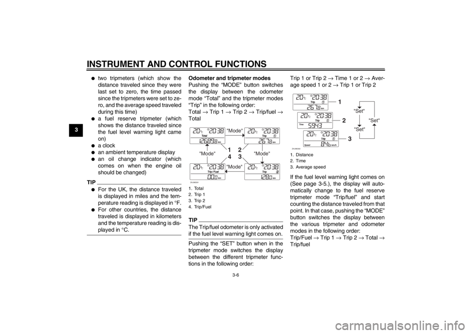
Odometer and tripmeter modes
Pushing the “MODE” button switches
the display between the odometer
mode “Total” and the tripmeter modes
“Trip” in the following order:
Total → Trip 1 → Trip 2 → Trip/fuel →
TotalTIPThe Trip/fuel odometer is only activated
if the fuel level warning light comes on.Pushing the “SET” button when in the
tripmeter mode switches the display
between the different tripmeter func-
tions in the following order:Trip 1 or Trip 2 → Time 1 or 2 → Aver-
age speed 1 or 2 → Trip 1 or Trip 2
If the fuel level warning light comes on
(See page 3-5.), the display will auto-
matically change to the fuel reserve
tripmeter mode “Trip/fuel” and start
counting the distance traveled from that
point. In that case, pushing the “MODE”
button switches the display between
the various tripmeter and odometer
modes in the following order:
Trip/Fuel → Trip 1 → Trip 2 → Total →
Trip/fuel1. Total
2. Trip 1
3. Trip 2
4. Trip/Fuel
"Mode"
"Mode"
"Mode"
"Mode"
1
2
3
4
ZAUM0391
1. Distance
2. Time
3. Average speed
"Set"
"Set""Set"
12
3
ZAUM0392
U16PE3E0.book Page 6 Tuesday, June 19, 2012 5:17 PM
Page 25 of 86
INSTRUMENT AND CONTROL FUNCTIONS
3-9
3
EAUS1020
Dimmer switch “ / ”
Set this switch to “ ” for the high
beam and to “ ” for the low beam.
With the headlight on low beam, press
this switch downwards to flash the
headlight.
EAU12460
Turn signal switch “ / ”
To signal a right-hand turn, push this
switch to “ ”. To signal a left-hand
turn, push this switch to “ ”. When re-
leased, the switch returns to the center
position. To cancel the turn signal
lights, push the switch in after it has re-
turned to the center position.
EAU12500
Horn switch “ ”
Press this switch to sound the horn.
EAU12721
Start switch “ ”
With the sidestand up, push this switch
while applying the front or rear brake to
crank the engine with the starter. See
page 5-1 for starting instructions prior
to starting the engine.
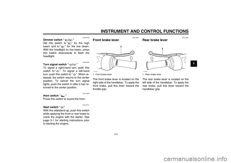
EAU12901
Front brake lever The front brake lever is located on the
right side of the handlebar. To apply the
front brake, pull this lever toward the
throttle grip.
EAU12951
Rear brake lever The rear brake lever is located on the
left side of the handlebar. To apply the
rear brake, pull this lever toward the
handlebar grip.
1. Front brake lever
1
ZAUM0791
1. Rear brake lever
1
ZAUM0085
U16PE3E0.book Page 9 Tuesday, June 19, 2012 5:17 PM
Page 26 of 86
INSTRUMENT AND CONTROL FUNCTIONS
3-10
3
EAUM2161
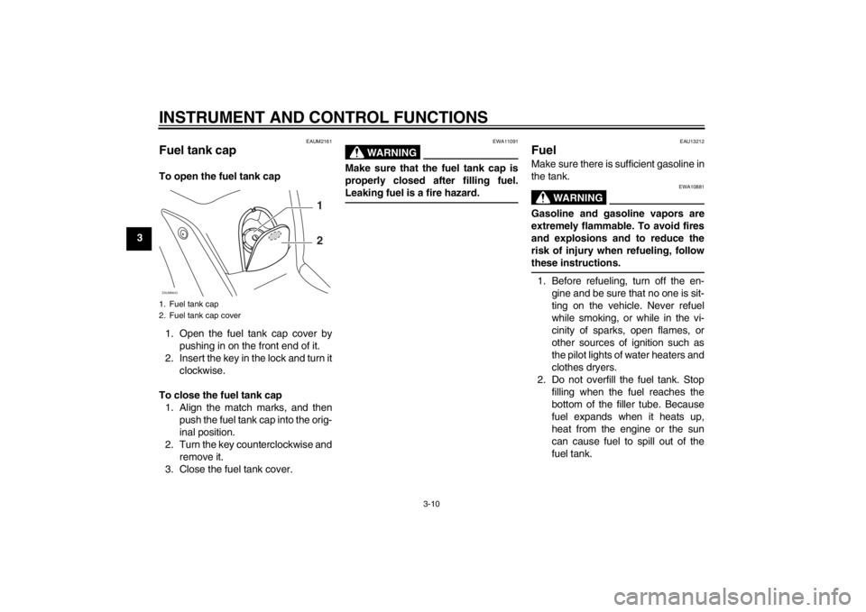
Fuel tank cap To open the fuel tank cap
1. Open the fuel tank cap cover by
pushing in on the front end of it.
2. Insert the key in the lock and turn it
clockwise.
To close the fuel tank cap
1. Align the match marks, and then
push the fuel tank cap into the orig-
inal position.
2. Turn the key counterclockwise and
remove it.
3. Close the fuel tank cover.
WARNING
EWA11091
Make sure that the fuel tank cap is
properly closed after filling fuel.
Leaking fuel is a fire hazard.
EAU13212
Fuel Make sure there is sufficient gasoline in
the tank.
WARNING
EWA10881
Gasoline and gasoline vapors are
extremely flammable. To avoid fires
and explosions and to reduce the
risk of injury when refueling, follow
these instructions.1. Before refueling, turn off the en-
gine and be sure that no one is sit-
ting on the vehicle. Never refuel
while smoking, or while in the vi-
cinity of sparks, open flames, or
other sources of ignition such as
the pilot lights of water heaters and
clothes dryers.
2. Do not overfill the fuel tank. Stop
filling when the fuel reaches the
bottom of the filler tube. Because
fuel expands when it heats up,
heat from the engine or the sun
can cause fuel to spill out of the
fuel tank.
1. Fuel tank cap
2. Fuel tank cap coverZAUM0643
1
2
U16PE3E0.book Page 10 Tuesday, June 19, 2012 5:17 PM
Page 33 of 86
INSTRUMENT AND CONTROL FUNCTIONS
3-17
3
WARNING
EWA10241
The vehicle must not be ridden with
the sidestand down, or if the side-
stand cannot be properly moved up
(or does not stay up), otherwise the
sidestand could contact the ground
and distract the operator, resulting
in a possible loss of control.
Yamaha’s ignition circuit cut-off
system has been designed to assist
the operator in fulfilling the respon-
sibility of raising the sidestand be-
fore starting off. Therefore, check
this system regularly and have a
Yamaha dealer repair it if it does not
function properly.
EAU45052
Ignition circuit cut-off system The ignition circuit cut-off system (com-
prising the sidestand switch and brake
light switches) has the following func-
tions.●
It prevents starting when the side-
stand is up, but neither brake is ap-
plied.
●
It prevents starting when either
brake is applied, but the sidestand
is still down.
●
It cuts the running engine when the
sidestand is moved down.
Periodically check the operation of the
ignition circuit cut-off system according
to the following procedure.
U16PE3E0.book Page 17 Tuesday, June 19, 2012 5:17 PM
Page 36 of 86

FOR YOUR SAFETY – PRE-OPERATION CHECKS
4-2
4
Rear brake Check operation.
If soft or spongy, have Yamaha dealer bleed hydraulic system.
Check brake pads for wear.
Replace if necessary.
Check fluid level in reservoir.
If necessary, add specified brake fluid to specified level.
Check hydraulic system for leakage.6-19, 6-20, 6-21
Throttle grip Make sure that operation is smooth.
Check throttle grip free play.
If necessary, have Yamaha dealer adjust throttle grip free play and lubricate cable
and grip housing.6-16, 6-23
Wheels and tires Check for damage.
Check tire condition and tread depth.
Check air pressure.
Correct if necessary.6-17, 6-19
Brake levers Make sure that operation is smooth.
Lubricate lever pivoting points if necessary.6-23
Centerstand, sidestand Make sure that operation is smooth.
Lubricate pivots if necessary.6-23
Chassis fasteners Make sure that all nuts, bolts and screws are properly tightened.
Tighten if necessary.—
Instruments, lights, signals
and switches Check operation.
Correct if necessary.—
Sidestand switch Check operation of ignition circuit cut-off system.
If system is not working correctly, have Yamaha dealer check vehicle.3-16 ITEM CHECKS PAGE
U16PE3E0.book Page 2 Tuesday, June 19, 2012 5:17 PM
Page 37 of 86

OPERATION AND IMPORTANT RIDING POINTS
5-1
5
EAU15951
Read the Owner’s Manual carefully to
become familiar with all controls. If
there is a control or function you do not
understand, ask your Yamaha dealer.
WARNING
EWA10271
Failure to familiarize yourself with
the controls can lead to loss of con-
trol, which could cause an accident
or injury.
EAU45310
TIPThis model is equipped with a lean an-
gle sensor to stop the engine in case of
a turnover. To start the engine after a
turnover, be sure to turn the main
switch to “OFF” and then to “ON”. Fail-
ing to do so will prevent the engine from
starting even though the engine will
crank when pushing the start switch.
EAUM2233
Starting the engine NOTICE
ECA10250
See page 5-4 for engine break-in in-
structions prior to operating the ve-
hicle for the first time.In order for the ignition circuit cut-off
system to enable starting, the side-
stand must be up.
See page 3-17 for more information.
1. Turn the key to “ON”.
The following warning lights and
indicator light should come on for a
few seconds, then go off.
●
Fuel level warning light
●
Engine trouble warning light
●
Immobilizer system indicator
light
NOTICE
ECA11833
If a warning or indicator light does
not come on initially when the key is
turned to “ON”, or if a warning or in-
dicator light remains on, see page
3-3 for the corresponding warning
and indicator light circuit check.2. Close the throttle completely.
U16PE3E0.book Page 1 Tuesday, June 19, 2012 5:17 PM
Page 40 of 86
OPERATION AND IMPORTANT RIDING POINTS
5-4
5
EAU16820
Tips for reducing fuel con-
sumption Fuel consumption depends largely on
your riding style. Consider the following
tips to reduce fuel consumption:●
Avoid high engine speeds during
acceleration.
●
Avoid high engine speeds with no
load on the engine.
●
Turn the engine off instead of let-
ting it idle for an extended length of
time (e.g., in traffic jams, at traffic
lights or at railroad crossings).
EAU16830
Engine break-in There is never a more important period
in the life of your engine than the period
between 0 and 1000 km (600 mi). For
this reason, you should read the follow-
ing material carefully.
Since the engine is brand new, do not
put an excessive load on it for the first
1000 km (600 mi). The various parts in
the engine wear and polish themselves
to the correct operating clearances.
During this period, prolonged full-throt-
tle operation or any condition that might
result in engine overheating must be
avoided.
EAUM2281
0–500 km (0–300 mi)
Avoid prolonged operation above 1/3
throttle.
500–1000 km (300–600 mi)
Avoid prolonged operation above 1/2
throttle. NOTICE: After 1000 km (600
mi) of operation, the engine oil and
final transmission oil must be
changed, and the engine oil filter el-
ement replaced.
[ECAM1091]
1000 km (600 mi) and beyond
The vehicle can now be operated nor-
mally.NOTICE
ECA10270
If any engine trouble should occur
during the engine break-in period,
immediately have a Yamaha dealer
check the vehicle.
U16PE3E0.book Page 4 Tuesday, June 19, 2012 5:17 PM
Page 46 of 86

PERIODIC MAINTENANCE AND ADJUSTMENT
6-5
6
9*Steering bearings Check bearing play and steering
for roughness.√√√√√
Lubricate with lithium-soap-based
grease.Every 24000 km (14000 mi)
10*Chassis fasteners Make sure that all nuts, bolts and
screws are properly tightened.√√√√√
11Front brake lever
pivot shaft Lubricate with silicone grease.√√√√√
12Rear brake lever
pivot shaft Lubricate with silicone grease.√√√√√
13Sidestand, center-
stand Check operation.
Lubricate with lithium-soap-based
grease.√√√√√
14*Sidestand switch Check operation.√√√√√√
15*Front fork Check operation and for oil leak-
age.√√√√
16*Shock absorber as-
semblies Check operation and shock ab-
sorbers for oil leakage.√√√√
17 Engine oil Change. (See page 3-3.)√When the oil change indicator light comes on [5000 km (3000 mi)
after the initial 1000 km (600 mi) and every 6000 km (3500 mi)
thereafter]
Check oil level and vehicle for oil
leakage.Every 3000 km (1800 mi)√
18Engine oil filter ele-
ment Replace.√√√ NO. ITEM CHECK OR MAINTENANCE JOBODOMETER READING
ANNUAL
CHECK 1000 km
(600 mi)6000 km
(3500 mi)12000 km
(7000 mi)18000 km
(10500 mi)24000 km
(14000 mi)
U16PE3E0.book Page 5 Tuesday, June 19, 2012 5:17 PM