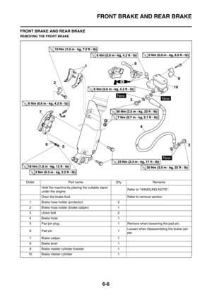
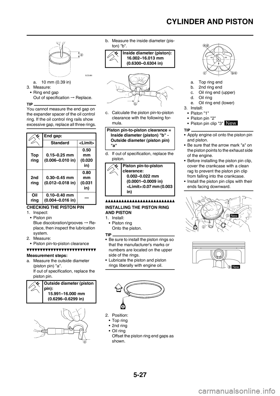
Page 129 of 232

5-26
CYLINDER AND PISTON
REMOVING THE PISTON AND
PISTON RING
1. Remove:
• Piston pin clip "1"
• Piston pin "2"
• Piston "3"
• Put identification marks on each
piston head for reference during re-
installation.
• Before removing each piston pin,
deburr the clip groove and pin hole
area. If the piston pin groove is de-
burred and the piston pin is still dif-
ficult to remove, use the piston pin
puller set "4".
Do not use a hammer to drive the
piston pin out.
2. Remove:
• Piston ring "1"
Spread the end gaps apart while at
the same time lifting the piston ring
over the top of the piston crown, as
shown in the illustration.
CHECKING THE CYLINDER AND
PISTON
1. Inspect:
• Cylinder and piston walls
Vertical scratches→Replace cyl-
inder and piston.
2. Measure:
• Piston-to-cylinder clearance
Measurement steps:
a. Measure the cylinder bore "C"
with a cylinder bore gauge.
Measure the cylinder bore "C" in par-
allel to and at right angles to the
crankshaft. Then, find the average of
the measurements.
b. If out of specification, replace the
cylinder, and replace the piston
and piston rings as set.
c. Measure the piston skirt diameter
"P" with a micrometer.
a. 8 mm (0.31 in) from the piston
bottom edged. If out of specification, replace the
piston and piston rings as a set.
e. Calculate the piston-to-cylinder
clearance with following formula:
f. If out of specification, replace the
cylinder, and replace the piston
and piston rings as set.
CHECKING THE PISTON RING
1. Measure:
• Ring side clearance
Use a feeler gauge "1".
Out of specification→Replace the
piston and rings as a set.
Clean carbon from the piston ring
grooves and rings before measuring
the side clearance.
2. Position:
• Piston ring
(in cylinder)
Insert a ring into the cylinder and
push it approximately 10 mm (0.39 in)
into the cylinder. Push the ring with
the piston crown so that the ring will
be at a right angle to the cylinder
bore.
Piston pin puller set:
YU-1304/90890-01304
Cylinder bore
"C"77.00–77.01
mm
(3.0315–3.0319
in)
Taper limit "T"0.05 mm (0.002
in)
Out of round
"R"0.05 mm (0.002
in)
"C" = Maximum D
"T" = (Maximum D
1 or D2) - (Max-
imum D
5 or D6)
"R" = (Maximum D
1, D3 or D5) -
(Minimum D
2, D4 or D6)
Piston size "P"
Standard76.955–76.970
mm
(3.0297–3.0303
in)
Piston-to-cylinder clearance =
Cylinder bore "C" - Piston skirt
diameter "P"
Piston-to-cylinder clear-
ance:
0.030–0.055 mm
(0.0012–0.0022 in)
:0.1 mm (0.004
in)
Side clearance:
Standard
Top
ring0.030–0.065
mm
(0.0012–0.0026
in)0.12
mm
(0.005
in)
2nd
ring0.020–0.055
mm
(0.0008–0.0022
in)0.12
mm
(0.005
in)
Page 130 of 232

5-27
CYLINDER AND PISTON
a. 10 mm (0.39 in)
3. Measure:
• Ring end gap
Out of specification→Replace.
You cannot measure the end gap on
the expander spacer of the oil control
ring. If the oil control ring rails show
excessive gap, replace all three rings.
CHECKING THE PISTON PIN
1. Inspect:
• Piston pin
Blue discoloration/grooves→Re-
place, then inspect the lubrication
system.
2. Measure:
• Piston pin-to-piston clearance
Measurement steps:
a. Measure the outside diameter
(piston pin) "a".
If out of specification, replace the
piston pin.b. Measure the inside diameter (pis-
ton) "b".
c. Calculate the piston pin-to-piston
clearance with the following for-
mula.
d. If out of specification, replace the
piston.
INSTALLING THE PISTON RING
AND PISTON
1. Install:
•Piston ring
Onto the piston.
• Be sure to install the piston rings so
that the manufacturer's marks or
numbers are located on the upper
side of the rings.
• Lubricate the piston and piston
rings liberally with engine oil.
2. Position:
•Top ring
• 2nd ring
• Oil ring
Offset the piston ring end gaps as
shown.a. Top ring end
b. 2nd ring end
c. Oil ring end (upper)
d. Oil ring
e. Oil ring end (lower)
3. Install:
• Piston "1"
• Piston pin "2"
• Piston pin clip "3"
• Apply engine oil onto the piston pin
and piston.
• Be sure that the arrow mark "a" on
the piston points to the exhaust side
of the engine.
• Before installing the piston pin clip,
cover the crankcase with a clean
rag to prevent the piston pin clip
from falling into the crankcase.
• Install the piston pin clips with their
ends facing downward.End gap:
Standard
Top
ring0.15–0.25 mm
(0.006–0.010 in)0.50
mm
(0.020
in)
2nd
ring0.30–0.45 mm
(0.012–0.018 in)0.80
mm
(0.031
in)
Oil
ring0.10–0.40 mm
(0.004–0.016 in)—
Outside diameter (piston
pin):
15.991–16.000 mm
(0.6296–0.6299 in)
Inside diameter (piston):
16.002–16.013 mm
(0.6300–0.6304 in)
Piston pin-to-piston clearance =
Inside diameter (piston) "b" -
Outside diameter (piston pin)
"a"
Piston pin-to-piston
clearance:
0.002–0.022 mm
(0.0001–0.0009 in)
:0.07 mm (0.003
in)
New
Page 131 of 232
5-28
CYLINDER AND PISTON
INSTALLING THE CYLINDER
1. Lubricate:
•Piston
• Piston ring
• Cylinder
Apply a liberal coating of engine oil.
2. Install:
• Dowel pin "1"
• O-ring "2"
Apply the lithium soap base grease
on the O-ring.
3. Install:
• Cylinder gasket "1"
• Cylinder "2"
Install the cylinder with one hand
while compressing the piston rings
with the other hand.
• Pass the timing chain "3"
through the timing chain cavity.
• Be careful not to damage the tim-
ing chain guide "4" during instal-
lation.
4. Install:
• Bolt (cylinder) "5"
Bolt (cylinder):
10 Nm (1.0 m•kg, 7.2
ft•lb)
Page 132 of 232
5-29
CLUTCH
CLUTCH
REMOVING THE CLUTCH
Order Part name Q'ty Remarks
Drain the engine oil. Refer to "CHANGING THE ENGINE OIL"
section in the CHAPTER 3.
Brake pedal Refer to "ENGINE REMOVAL" section.
Clutch cable Disconnect at engine side.
1 Clutch cover 1
2 Clutch spring 5
3 Pressure plate 1
4 Push rod 1 1
5 Circlip 1
6 Washer 1
7 Bearing 1
8Ball 1
9 Push rod 2 1
10 Friction plate 9
11 Clutch plate 8
12 Cushion spring 1
13 Seat plate 1
Page 133 of 232
5-30
CLUTCH
14 Nut (clutch boss) 1 Refer to removal section.
15 Lock washer 1 Refer to removal section.
16 Clutch boss 1 Refer to removal section.
17 Thrust washer 1
18 Primary driven gear 1
19 Push lever shaft 1 Order Part name Q'ty Remarks
Page 134 of 232

5-31
CLUTCH
REMOVING THE CLUTCH BOSS
1. Remove:
•Nut "1"
• Lock washer "2"
• Clutch boss "3"
Straighten the lock washer tab and
use the clutch holding tool "4" to hold
the clutch boss.
A. For USA and CDN
B. Except for USA and CDN
CHECKING THE CLUTCH
HOUSING AND BOSS
1. Inspect:
• Clutch housing "1"
Cracks/wear/damage→Replace.
• Clutch boss "2"
Scoring/wear/damage→Replace.
CHECKING THE PRIMARY DRIVEN
GEAR
1. Check:
• Circumferential play
Free play exists→Replace.
• Gear teeth "a"
Wear/damage→Replace.CHECKING THE CLUTCH
SPRINGS
1. Measure:
• Clutch spring free length "a"
Out of specification→Replace
springs as a set.
CHECKING THE FRICTION
PLATES
1. Measure:
• Friction plate thickness
Out of specification→Replace
friction plate as a set.
Measure at all four points.
CHECKING THE CLUTCH PLATES
1. Measure:
• Clutch plate warpage
Out of specification→Replace
clutch plate as a set.
Use a surface plate "1" and thick-
ness gauge "2".CHECKING THE PUSH LEVER
SHAFT
1. Inspect:
• Push lever shaft "1"
Wear/damage→Replace.
CHECKING THE PUSH ROD
1. Inspect:
• Push rod 1 "1"
• Bearing "2"
• Washer "3"
• Push rod 2 "4"
•Ball "5"
Wear/damage/bend→Replace.
INSTALLING THE PUSH LEVER
SHAFT
1. Install:
• Push lever shaft "1"
• Bolt (push lever shaft) "2"
• Apply the lithium soap base grease
on the oil seal lip.
• Apply the engine oil on the push le-
ver shaft.
• Fit the seat plate "3" in the groove
"a" of the push lever shaft and tight-
en the bolt (seat plate).
Clutch holding tool:
YM-91042/90890-04086
Clutch spring free
length:
37.0 mm (1.46 in)
: 36.0 mm (1.42
in)
Friction plate thickness:
2.9–3.1 mm
(0.114–0.122 in)
: 2.7 mm (0.106
in)
Warp limit:
0.1 mm (0.004 in)
Bolt (push lever shaft):
10 Nm (1.0 m•kg, 7.2
ft•lb)
Page 135 of 232

5-32
CLUTCH
INSTALLING THE CLUTCH
1. Install:
• Primary driven gear "1"
• Thrust washer "2"
• Clutch boss "3"
Apply the engine oil on the primary
driven gear inner circumference.
2. Install:
• Lock washer "1"
• Nut (clutch boss) "2"
Use the clutch holding tool "3" to hold
the clutch boss.
A. For USA and CDN
B. Except for USA and CDN
3. Bend the lock washer "1" tab.
4. Install:
• Seat plate "1"
• Cushion spring "2"
• Install the seat plate with its cham-
fered portion "a" facing the clutch
boss "3".
• Install the seat plate so that it is not
caught on the step "b".
• Install the cushion spring with the
paint "c" facing out.
5. Install:
• Friction plate 1 "1"
• Clutch plate 1 "2"
• Friction plate 2 "3"
• Clutch plate 2 "4"
• Install the clutch plates and friction
plates alternately on the clutch
boss, starting with a friction plate
and ending with a friction plate.
• Use the friction plates 1 for the first
and final while paying attention to
the difference in surface pattern.
• Apply the engine oil on the friction
plates and clutch plates.
• Unlike the clutch plate 2, the clutch
plate 1 has no surface gloss. Use
the clutch plate 1 for the first while
paying attention to the difference in
surface gloss.
6. Install:
•Bearing "1"
• Washer "2"
• Circlip "3"
To push rod 1 "4".
Apply the engine oil on the bearing
and washer.
7. Install:
• Push rod 2 "1"
•Ball "2"
• Push rod 1 "3"
Apply the engine oil on the push rod
1, 2 and ball.
8. Install:
• Pressure plate "1"
9. Install:
• Clutch spring "1"
• Bolt (clutch spring) "2"
Tighten the bolts in stage, using a
crisscross pattern.
Nut (clutch boss):
75 Nm (7.5 m•kg, 54
ft•lb)
Clutch holding tool:
YM-91042/90890-04086
Bolt (clutch spring):
10 Nm (1.0 m•kg, 7.2
ft•lb)
Page 136 of 232
5-33
CLUTCH
10. Install:
• Dowel pin "1"
• Gasket (clutch cover) "2"
11. Install:
• Clutch cover "1"
• Bolt (clutch cover)
Tighten the bolts in stage, using a
crisscross pattern.
Bolt (clutch cover):
10 Nm (1.0 m•kg, 7.2
ft•lb)