Page 33 of 98
 stops the
engine when the switch is pushed.
EJU31163Engine shut-off switch“”
The engine shut-of")
Control function operation
27
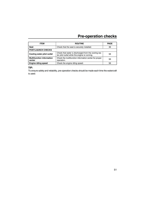
EJU31152Engine stop switch“”
The engine stop switch (red button) stops the
engine when the switch is pushed.
EJU31163Engine shut-off switch“”
The engine shut-off switch automatically
stops the engine when the clip, on the end of
the engine shut-off cord (lanyard), is removed
from the switch, such as if the operator falls off
the watercraft.
Insert the clip under the engine shut-off switch
before starting the engine.
When the engine is not running, remove the
clip from the engine shut-off switch to preventaccidental starting or unauthorized operation
by children or others.
EJU36286Start switch“”
NOTICE
ECJ01310
Do not run the engine over 4000 r/min on
land. Also, do not run the engine for more
than 15 seconds without supplying water,
otherwise the engine could overheat.
The start switch (green button) starts the en-
gine when the switch is pushed.
Release the start switch as soon as the en-
gine starts to run. If the engine does not start
in 5 seconds, release the start switch, wait 15
seconds, and then try again. NOTICE: Never
push the start switch while the engine is
running. Do not operate the start switch
for more than 5 seconds, otherwise the
battery will be discharged and the engine
1Engine stop switch
1Engine shut-off switch
2Clip
3Engine shut-off cord (lanyard)
1
STOP
312
UF2M71E0.book Page 27 Wednesday, June 29, 2011 9:27 AM
Page 34 of 98
![YAMAHA VXR 2012 Owners Manual Control function operation
28
will not start. Also, the starter motor could
be damaged.
[ECJ01040]
The engine will not start under any of the fol-
lowing conditions:
�Lock mode of the Yamaha Security](/manual-img/51/52219/w960_52219-33.png "YAMAHA VXR 2012 Owners Manual Control function operation
28
will not start. Also, the starter motor could
be damaged.
[ECJ01040]
The engine will not start under any of the fol-
lowing conditions:
�Lock mode of the Yamaha Security")
Control function operation
28
will not start. Also, the starter motor could
be damaged.
[ECJ01040]
The engine will not start under any of the fol-
lowing conditions:
�Lock mode of the Yamaha Security System
has been selected. (See page 26 for
Yamaha Security System setting proce-
dures.)
�Clip is removed from the engine shut-off
switch.
�Throttle lever is squeezed.EJU31211Throttle lever
The throttle lever increases the engine speed
when the lever is squeezed.
The throttle lever returns automatically to its
fully closed (idle) position when released.
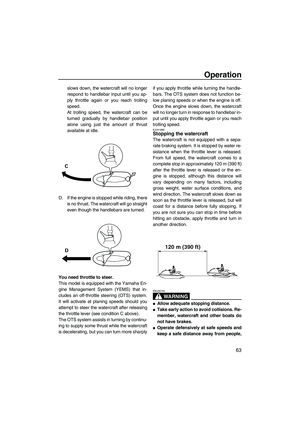
EJU31261Steering system
By turning the handlebars in the direction you
wish to travel, the angle of the jet thrust nozzle
is changed, and the direction of the watercraft
is changed accordingly.
Since the strength of the jet thrust determines
the speed and degree of a turn, throttle must
always be applied when attempting a turn, ex-
cept at trolling speed.
This model is equipped with the Yamaha En-
gine Management System (YEMS) that in-
cludes an off-throttle steering (OTS) system.
It will activate at planing speeds should you
attempt to steer the watercraft after releasing
the throttle lever. The OTS system assists in
turning by continuing to supply some thrust
while the watercraft is decelerating, but you
can turn more sharply if you apply throttle
while turning the handlebars. The OTS sys-
tem does not function below planing speeds
or when the engine is off. Once the engine
slows down, the watercraft will no longer turn
1Start switch
1Throttle lever
START
1
1
1Handlebar
2Jet thrust nozzle
2
1
UF2M71E0.book Page 28 Wednesday, June 29, 2011 9:27 AM
Page 35 of 98

Control function operation
29
in response to handlebar input until you apply
throttle again or you reach trolling speed.
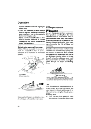
EJU35974Cooling water pilot outlet
When the engine is running, some of the cool-
ing water that is circulated in the engine is dis-
charged from the cooling water pilot outlet.
There is a cooling water pilot outlet on the port
(left) side of the watercraft. To check for prop-
er operation of the cooling system, make sure
that water is being discharged from the cool-
ing water pilot outlet. If water is not being dis-
charged from the outlet, stop the engine and
check the jet intake for clogging. (See page
85 for information on the jet intake.)
TIP:
�It will take about 60 seconds for the water to
reach the outlet after the engine is started.
�Water discharge may not be constant when
the engine is running at idling speed. If this
occurs, apply a little throttle to make sure
that water discharges properly.
EJU40322Water separator
The water separator prevents water from en-
tering the fuel tank by collecting any water that
has entered the fuel tank breather hose if the
watercraft was capsized.If water has collected in the water separator,
drain it by loosening the drain screw.
To drain water from the water separator:
(1) Place a drain pan or dry cloth under the
water separator.
(2) Gradually loosen the drain screw to drain
the water. Catch the draining water in the
drain pan or soak it up with the dry cloth
so that it does not spill into the engine
compartment. If any water spills into the
watercraft, be sure to wipe it up with a dry
cloth.
(3) Securely tighten the drain screw until it
stops.
1Cooling water pilot outlet
1
1Water separator
1Drain screw
1
1
UF2M71E0.book Page 29 Wednesday, June 29, 2011 9:27 AM
Page 36 of 98

Watercraft operation
30
EJU40011
Watercraft operation functions
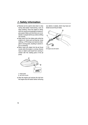
EJU40520Reverse system
WARNING
EWJ01230
�Do not use the reverse function to slow
down or stop the watercraft as it could
cause you to lose control, be ejected, or
impact the handlebars.
�Make sure that there are no obstacles or
people behind you before shifting into
reverse.
�Do not touch the reverse gate while the
shift lever is being operated, otherwise
you could be pinched.
When the shift lever is moved to the reverse
position, the reverse gate lowers and deflects
the water jet being discharged from the jet
thrust nozzle. This allows the watercraft to
move in reverse.
To shift into reverse:
(1) Release the throttle lever and let the en-
gine speed return to idle.
(2) Pull the shift lever rearward until it stops
in the reverse position. The reverse gatewill lower and the watercraft will start
moving in reverse at trolling speed.
To shift into forward:
(1) Release the throttle lever and let the en-
gine speed return to idle.
(2) Push the shift lever forward until it stops
in the forward position. The reverse gate
will rise and the watercraft will start mov-
ing forward at trolling speed.
1Shift lever
2Reverse position
3Forward position
1Reverse gate
2Forward position
3Reverse position
1
23
13
2
UF2M71E0.book Page 30 Wednesday, June 29, 2011 9:27 AM
Page 37 of 98

Watercraft operation
31
EJU40000
Watercraft operation modes
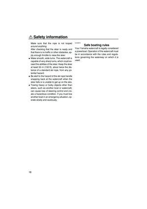
EJU41960Low RPM Mode
The Low RPM Mode is a function that limits
the maximum engine speed to approximately
70% of the maximum engine speed in the nor-
mal mode.
The Low RPM Mode can only be activated
and deactivated by operating the remote con-
trol transmitter that is included with this water-
craft. (See page 25 for information on the
remote control transmitter.)
TIP:
The Low RPM Mode can only be activated
when the engine is stopped in the unlock
mode of the Yamaha Security System.
Activating and deactivating the Low RPM
Mode
Activation of the Low RPM Mode will be con-
firmed by the number of beeps when the re-
mote control transmitter is operated, and by
the “L-MODE” indicator light of the multifunc-
tion information center. (See page 33 for infor-
mation on the multifunction information
center.)
TIP:
If the remote control transmitter is operated
while the multifunction information center is in
the standby state, the center performs the ini-
tial operation, and then the setting is selected.
To activate the Low RPM Mode:
Push the “L-Mode” (unlock) button on the re-
mote control transmitter for more than 4 sec-
onds. Once the beeper sounds three times
and the “SECURITY” indicator light blinks
three times, then comes on, the “L-MODE” in-
dicator light comes on and the Low RPM
Mode is activated.
TIP:
If the Low RPM Mode is activated immediate-
ly after the information display turns off, the
“L-MODE” indicator light will not come on. The
1Remote control transmitter
Number of
beepsLow RPM Mode
operation“L-
MODE”
indicator
light
ActivatedComes
on
Deactivated Goes off
UF2M71E0.book Page 31 Wednesday, June 29, 2011 9:27 AM
Page 38 of 98
Watercraft operation
32
“L-MODE” indicator light will come on when
the engine is started.
To deactivate the Low RPM Mode:
Push the “L-Mode” (unlock) button on the re-
mote control transmitter for more than 4 sec-
onds. Once the beeper sounds two times and
the “SECURITY” indicator light blinks two
times, then comes on, the “L-MODE” indicator
light goes off and the Low RPM Mode is deac-
tivated. When the Low RPM Mode is deacti-
vated, the watercraft returns to the normal
operation mode.
1“L-Mode” (unlock) button
1“SECURITY” indicator light
2“L-MODE” indicator light
L-Mode1
12
UF2M71E0.book Page 32 Wednesday, June 29, 2011 9:27 AM
Page 39 of 98

Instrument operation
33
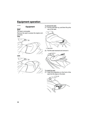
EJU41850
Multifunction information
center
The multifunction information center displays
various watercraft information.
Multifunction information center initial op-
eration
When the multifunction information center is
activated, all of the display segments and the
“SECURITY” indicator light come on. After 2
seconds, the warning indicators in the infor-
mation display go off, and then the center
starts to operate normally.
TIP:
The “SECURITY” indicator light will go off
when the engine is started.
Multifunction information center standby
state
If the multifunction information center does
not receive any operation input within 25 sec-
onds after the engine stops, the center will
turn off and enter a standby state. When the
engine is started again, the displays return to
their state before the center turned off, and
then the center starts to operate normally.
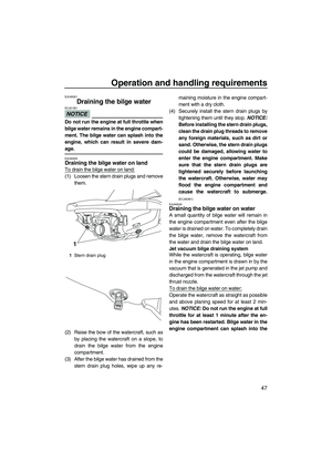
EJU35024Information display
The information display shows watercraft op-
erating conditions.
EJU31503Speedometer
The speedometer shows the watercraft speed
against water.
By switching the display units, the speed can
be shown in kilometers per hour “km/h” or
miles per hour “mph”.
TIP:
“mph” is selected as the display unit at the
Yamaha factory.
1“SECURITY” indicator light
2Select button
3Information display
4“L-MODE” indicator light
5“WARNING” indicator light
21345
1Tachometer
2Speedometer
3Hour meter/voltmeter
4Fuel level meter
5Check engine warning indicator
6Engine overheat warning indicator
7Oil pressure warning indicator
8Fuel level warning indicator
1Speedometer
1234
8765
1
UF2M71E0.book Page 33 Wednesday, June 29, 2011 9:27 AM
Page 40 of 98

Instrument operation
34
To switch the speedometer display units:
Push the select button for at least 1 second,
within 10 seconds after the multifunction infor-
mation center is activated. The speedometer
display changes.
EJU31463Tachometer
The tachometer shows the engine speed.
The outer numbers × 1000 r/min and display
segments on the meter show the engine
speed.
EJU31555Hour meter/voltmeter
The hour meter/voltmeter has both an hour
meter function and a voltmeter function. By
switching the meter, it can be used as either
an hour meter or a voltmeter.
TIP:
The hour meter is selected at the Yamaha
factory.
Hour meter
The hour meter shows the total number of
hours that the engine has been running since
the watercraft was new.
TIP:
The elapsed time will be kept even if the bat-
tery terminals have been disconnected.
To switch to the hour meter from the voltme-
ter:
Push the select button for at least 1 second af-
ter the multifunction information center is acti-
vated for more than 10 seconds. The display
switches to the hour meter from the voltmeter.
Voltmeter
The voltmeter shows the battery voltage.
1Speedometer
2Select button
1Tachometer
1
2
1
1Hour meter/voltmeter
1Hour meter
2Select button
1
1
2
UF2M71E0.book Page 34 Wednesday, June 29, 2011 9:27 AM


 button on the re-
mote control transmitter")