Page 135 of 172

8-46
8
EBU24060Valve clearance The valve clearance changes with use, resulting in
improper air-fuel mixture and/or engine noise. To
prevent this from occurring, the valve clearance
must be adjusted by a Yamaha dealer at the inter-
vals specified in the periodic maintenance and lu-
brication chart.EBU24071Adjusting the drive select lever safety
system cable The drive select lever safety system cable stretch-
es with use, which can result in improper function.
Therefore, the safety system cable should be
checked and adjusted by a Yamaha dealer at the
intervals specified in the periodic maintenance and
lubrication chart.EBU29601Brakes Replacement of brake components requires pro-
fessional knowledge. Brake service should be per-
formed by a Yamaha dealer.
WARNING
EWB02571Operating with improperly serviced or adjust-
ed brakes could lead to a loss in braking ability
and an accident.EBU27470Checking the front and rear brake pads The front and rear brake pads must be checked for
wear at the intervals specified in the periodic main-
tenance and lubrication chart. Each brake pad is
provided with a wear indicator groove, which al-
lows you to check the brake pad wear without hav-
ing to disassemble the brake. If a brake pad has
worn to the point that the wear indicator groove has
almost disappeared, have a Yamaha dealer re-
place the brake pads as a set.TIPThe wheels need to be removed to check the
brake pads. (See page 8-64.)
U1HP60E0.book Page 46 Monday, April 11, 2011 7:56 PM
Page 136 of 172
8-47
8Front brake
Rear brake
EBU27843Checking the rear brake hose protec-
tors The rear brake hose protectors must be checked
for wear at the intervals specified in the periodic
maintenance and lubrication chart. Each brake
hose protector is provided with a wear indicator. If
a protector wears to the point that its indicator be-
comes visible, have a Yamaha dealer replace the
protector.TIPThe wheels need to be removed to check the
brake hose protectors. (See page 8-64.)
1. Wear indicator groove
1. Wear indicator grooveU1HP60E0.book Page 47 Monday, April 11, 2011 7:56 PM
Page 144 of 172
8-55
8
EBU24963Checking the wheel hub bearings The front and rear wheel hub bearings must be
checked at the intervals specified in the periodic
maintenance and lubrication chart. If there is play
in a wheel hub or if a wheel does not turn smoothly,
have a Yamaha dealer check the wheel hub bear-
ings.EBU25022Checking the stabilizer bushes The stabilizer bushes must be checked for cracks
or damage at the intervals specified in the periodic
maintenance and lubrication chart.
Have a Yamaha dealer replace the stabilizer bush-
es if necessary.
EBU25052Lubricating the rear knuckle pivots The rear knuckle pivots must be lubricated at the
intervals specified in the periodic maintenance and
lubrication chart.TIPFor parts equipped with a grease nipple, use a
grease gun.Recommended lubricant:
Lithium-soap-based grease1. Grease nipple
U1HP60E0.book Page 55 Monday, April 11, 2011 7:56 PM
Page 149 of 172
8-60
8
The main fuse, the fuel injection system fuse, the
EPS fuse, and the fuse box are located under pan-
el A. (See page 8-10.)
If a fuse is blown, replace it as follows.
1. Turn the key to“” (off) and turn off all elec-
trical circuits.
NOTICEECB00640To prevent accidental short-circuiting, turn off
the main switch when checking or replacing a
fuse.2. Remove the blown fuse, and then install a
new fuse of the specified amperage.
WARNING! Always use a fuse of the spec-
ified rating, and never use a substitute ob-
ject in place of the proper fuse. An
improper fuse or a substitute object can
cause damage to the electrical system,
which could lead to a fire.
[EWB02172]
1. Auxiliary DC jack fuse
2. Four-wheel-drive motor fuse
3. Ignition fuse
4. Radiator fan fuse
5. Signaling system fuse
6. Headlight fuse
7. Spare fuseU1HP60E0.book Page 60 Monday, April 11, 2011 7:56 PM
Page 150 of 172
8-61
8
3. Turn the key to“” (on) and turn on the elec-
trical circuits to check if the devices operate.
4. If the fuse immediately blows again, have a
Yamaha dealer check the electrical system.
EBU27443Replacing a headlight bulb If a headlight bulb burns out, replace it as follows.
1. Remove the cover at the rear of the headlight
by pulling it off.
2. Remove the headlight bulb cover. Specified fuses:
Main fuse:
40.0 A
Headlight fuse:
10.0 A
Ignition fuse:
10.0 A
Four-wheel-drive motor fuse:
10.0 A
Signaling system fuse:
5.0 A
Auxiliary DC jack fuse:
10.0 A
Radiator fan fuse:
20.0 A
Fuel injection system fuse:
15.0 A
EPS fuse:
40.0 A1. Cover at the rear of the headlight
U1HP60E0.book Page 61 Monday, April 11, 2011 7:56 PM
Page 153 of 172
8-64
8 3. Remove the burnt-out bulb by pushing it in
and turning it counterclockwise.4. Insert a new bulb into the bulb holder, push it
in, and then turn it clockwise until it stops.
5. Install the bulb holder (together with the bulb)
by turning it clockwise.
6. Install the panel.
EBU25651Removing a wheel 1. Place the ATV on a level surface.
2. Loosen the wheel nuts.
3. Elevate the ATV and place a suitable stand
under the frame.
4. Remove the nuts from the wheel.
5. Remove the wheel.
1. Tail/brake light bulb holder
1. Tail/brake light bulb
1. Wheel nut
U1HP60E0.book Page 64 Monday, April 11, 2011 7:56 PM
Page 154 of 172
8-65
8
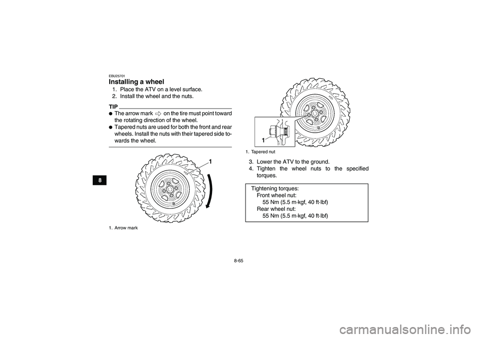
EBU25701Installing a wheel 1. Place the ATV on a level surface.
2. Install the wheel and the nuts.TIP�The arrow mark on the tire must point toward
the rotating direction of the wheel.�Tapered nuts are used for both the front and rear
wheels. Install the nuts with their tapered side to-
wards the wheel.
3. Lower the ATV to the ground.
4. Tighten the wheel nuts to the specified
torques.
1. Arrow mark
1
1. Tapered nutTightening torques:
Fro nt wh ee l nu t:
55 Nm (5.5 m·kgf, 40 ft·lbf)
Rear wheel nut:
55 Nm (5.5 m·kgf, 40 ft·lbf)
U1HP60E0.book Page 65 Monday, April 11, 2011 7:56 PM
Page 158 of 172

9-1
9
EBU25860
CLEANING AND STORAGE
EBU25881Cleaning Frequent, thorough cleaning of your ATV will not
only enhance its appearance but will improve its
general performance and extend the useful life of
many components.
1. Before cleaning the ATV:
a. Block off the end of the exhaust pipe to
prevent water entry. A plastic bag and
strong rubber band may be used.
b. Make sure the spark plug and all filler caps
are properly installed.
2. If the engine case is excessively greasy, apply
degreaser with a paint brush. Do not apply de-
greaser to the wheel axles.
3. Rinse the dirt and degreaser off with a garden
hose. Use only enough pressure to do the job.
WARNING! Wet brakes may have reduced
stopping ability, increasing the chance of
an accident. Test the brakes after washing.
Apply the brakes several times at slow
speeds to let friction dry out the linings.
[EWB02311]
NOTICE: Excessive water pressure
may cause water seepage and deteriora-tion of wheel bearings, brakes, transmis-
sion seals and electrical devices. Many
expensive repair bills have resulted from
improper high-pressure detergent applica-
tions such as those available in coin-oper-
ated car washers.
[ECB00711]
4. Once most of the dirt has been hosed off,
wash all surfaces with warm water and mild,
detergent-type soap. An old toothbrush or bot-
tle brush is handy for hard-to-reach places.
5. Rinse the ATV off immediately with clean wa-
ter and dry all surfaces with a chamois, clean
towel or soft absorbing cloth.
6. Clean the seat with a vinyl upholstery cleaner
to keep the cover pliable and glossy.
7. Automotive type wax may be applied to all
painted and chrome plated surfaces. Avoid
combination cleaner-waxes. Many contain
abrasives which may mar the paint or protec-
tive finish. When finished cleaning, start the
engine and let it idle for several minutes.
U1HP60E0.book Page 1 Monday, April 11, 2011 7:56 PM


If a fuse is blown, replace it as follows.
1. Turn the key to“” (")
 and turn on the elec-
trical circuits to check if the devices operate.
4. If the fuse immediately blows again, have a
Yamaha dealer check the electrical system.
EB")