Page 65 of 106

PERIODIC MAINTENANCE AND ADJUSTMENT
6-15
6
5. Remove the air filter case cover by
removing the screws. NOTICE:
When removing the air filter
case cover, be careful not to al-
low foreign objects to drop into
the air intake manifold.
[ECA12881]
6. Pull the air filter element out. 7. Insert a new air filter element into
the air filter case. NOTICE: Make
sure that the air filter element is
properly seated in the air filter
case. The engine should never
be operated without the air filter
element installed, otherwise the
piston(s) and/or cylinder(s) may
become excessively worn.
[ECA10481]
8. Install the air filter case cover by in- stalling the screws.
9. Place the fuel tank in the original position. Make sure that the fuel
hoses are properly connected and
routed, and not pinched. Be sure
to place the fuel tank breather hose and the fuel tank overflow
hose in the original position.
WARNING! Before placing the fuel tank in the original position,
make sure that the fuel hoses
are not damaged. If any fuel
hose is damaged, do not start
the engine but have a Yamaha
dealer replace the hose, other-
wise fuel may leak, creating a
fire hazard.
[EWA11361]
FZ1-N
1. Screw
2. Air filter case cover
1. Air filter element
2. Air intake manifold
1. Fuel tank breather hose
2. Original position (paint mark)
3. Fuel tank overflow hose
3
21
U1ECE1E0.book Page 15 Monday, August 8, 2011 11:52 AM
Page 66 of 106
PERIODIC MAINTENANCE AND ADJUSTMENT
6-16
6FZ1-NA
FZ1-NA
10. Install the fuel tank bolts.
11. Place the fuel tank cowling in the original position, and then install
the fuel tank cowling bolts. 12. Install the rider seat.
EAU34301
Adjusting the engine idling
speed The engine idling speed must be
checked and, if necessary, adjusted as
follows at the intervals specified in the
periodic maintenance and lubrication
chart.
The engine should be warm before
making this adjustment.
Check the engine idling speed and, if
necessary, adjust it to specification by
turning the idle adjusting screw. To in-
crease the engine idling speed, turn the
screw in direction (a). To decrease the
engine idling speed, turn the screw in
direction (b).
1. Fuel tank overflow hose
2. Original position (paint mark)
1. Fuel tank breather hose
2. Original position (paint mark)
21
1
2
1. Idle adjusting screw
U1ECE1E0.book Page 16 Monday, August 8, 2011 11:52 AM
Page 67 of 106
PERIODIC MAINTENANCE AND ADJUSTMENT
6-17
6
TIPIf the specified idling speed cannot be
obtained as described above, have a
Yamaha dealer make the adjustment.
EAU21384
Checking the throttle grip free
play The throttle grip free play should mea-
sure 3.0–5.0 mm (0.12–0.20 in) at the
inner edge of the throttle grip. Periodi-
cally check the throttle grip free play
and, if necessary, have a Yamaha deal-
er adjust it.
EAU21401
Valve clearance The valve clearance changes with use,
resulting in improper air-fuel mixture
and/or engine noise. To prevent this
from occurring, the valve clearance
must be adjusted by a Yamaha dealer
at the intervals specified in the periodic
maintenance and lubrication chart.
Engine idling speed: 1100–1300 r/min
1. Throttle grip free play
U1ECE1E0.book Page 17 Monday, August 8, 2011 11:52 AM
Page 68 of 106

PERIODIC MAINTENANCE AND ADJUSTMENT
6-18
6
EAU21775
Tires To maximize the performance, durabil-
ity, and safe operation of your motorcy-
cle, note the following points regarding
the specified tires.
Tire air pressure
The tire air pressure should be checked
and, if necessary, adjusted before each
ride.
WARNING
EWA10503
Operation of this vehicle with im-
proper tire pressure may cause se-
vere injury or death from loss of
control.●
The tire air pressure must be
checked and adjusted on cold
tires (i.e., when the temperature
of the tires equals the ambient
temperature).
●
The tire air pressure must be ad-
justed in accordance with the
riding speed and with the total
weight of rider, passenger, car-
go, and accessories approved
for this model.
WARNING
EWA10511
Never overload your vehicle. Opera-
tion of an overloaded vehicle could
cause an accident.
Tire inspection
The tires must be checked before each
ride. If the center tread depth reaches
the specified limit, if the tire has a nail or
glass fragments in it, or if the sidewall is
cracked, have a Yamaha dealer re-
place the tire immediately.TIPThe tire tread depth limits may differ
from country to country. Always comply
with the local regulations.
Tire air pressure (measured on cold
tires):0–90 kg (0–198 lb):Front:
250 kPa (2.50 kgf/cm², 36 psi)
Rear: 290 kPa (2.90 kgf/cm², 42 psi)
FZ1-N 90–196 kg (198–432 lb)
FZ1-NA 90–189 kg (198–417 lb): Front:
250 kPa (2.50 kgf/cm², 36 psi)
Rear: 290 kPa (2.90 kgf/cm², 42 psi)
High-speed riding: Front:250 kPa (2.50 kgf/cm², 36 psi)
Rear: 290 kPa (2.90 kgf/cm², 42 psi)
Maximum load*:
FZ1-N 196 kg (432 lb)
FZ1-NA 189 kg (417 lb)
* Total weight of rider, passenger, car-
go and accessories
1. Tire sidewall
2. Tire tread depthMinimum tire tread depth (front and
rear): 1.6 mm (0.06 in)
U1ECE1E0.book Page 18 Monday, August 8, 2011 11:52 AM
Page 69 of 106

PERIODIC MAINTENANCE AND ADJUSTMENT
6-19
6
WARNING
EWA10471
●
Have a Yamaha dealer replace
excessively worn tires. Besides
being illegal, operating the vehi-
cle with excessively worn tires
decreases riding stability and
can lead to loss of control.
●
The replacement of all wheel
and brake-related parts, includ-
ing the tires, should be left to a
Yamaha dealer, who has the necessary professional knowl-
edge and experience to do so.
●
Ride at moderate speeds after
changing a tire since the tire
surface must first be “broken
in” for it to develop its optimal
characteristics.
Tire information
This motorcycle is equipped with tube-
less tires, tire air valves and cast
wheels.
WARNING
EWA10481
●
The front and rear tires should
be of the same make and de-
sign, otherwise the handling
characteristics of the motorcy-
cle may be different, which
could lead to an accident.
●
Always make sure that the valve
caps are securely installed to
prevent air pressure leakage.
●
Use only the tire valves and
valve cores listed below to
avoid tire deflation during a
high-speed ride.
After extensive tests, only the tires list-
ed below have been approved for this
model by Yamaha Motor Co., Ltd.
WARNING
EWA10600
This motorcycle is fitted with super-
high-speed tires. Note the following
points in order to make the most ef-
ficient use of these tires.
1. Tire air valve
2. Tire air valve core
3. Tire air valve cap with seal
Front tire: Size: 120/70 ZR17M/C (58W)
Manufacturer/model: DUNLOP/D221FA
Rear tire:
Size: 190/50 ZR17M/C (73W)
Manufacturer/model:
DUNLOP/D221G
FRONT and REAR: Tire air valve:
TR412
Va l ve c o r e : #9100 (original)
U1ECE1E0.book Page 19 Monday, August 8, 2011 11:52 AM
Page 70 of 106

PERIODIC MAINTENANCE AND ADJUSTMENT
6-20
6
●
Use only the specified replace-
ment tires. Other tires may run
the danger of bursting at super
high speeds.
●
Brand-new tires can have a rela-
tively poor grip on certain road
surfaces until they have been
“broken in”. Therefore, it is ad-
visable before doing any high-
speed riding to ride conserva-
tively for approximately 100 km
(60 mi) after installing a new tire.
●
The tires must be warmed up
before a high-speed run.
●
Always adjust the tire air pres-
sure according to the operating
conditions.
EAU21962
Cast wheels To maximize the performance, durabil-
ity, and safe operation of your vehicle,
note the following points regarding the
specified wheels.●
The wheel rims should be checked
for cracks, bends, warpage or oth-
er damage before each ride. If any
damage is found, have a Yamaha
dealer replace the wheel. Do not
attempt even the smallest repair to
the wheel. A deformed or cracked
wheel must be replaced.
●
The wheel should be balanced
whenever either the tire or wheel
has been changed or replaced. An
unbalanced wheel can result in
poor performance, adverse han-
dling characteristics, and a short-
ened tire life.
EAU22081
Adjusting the clutch lever free
play The clutch lever free play should mea-
sure 10.0–15.0 mm (0.39–0.59 in) as
shown. Periodically check the clutch le-
ver free play and, if necessary, adjust it
as follows.
To increase the clutch lever free play,
turn the clutch lever free play adjusting
bolt in direction (a). To decrease the
clutch lever free play, turn the adjusting
bolt in direction (b).1. Clutch lever free play adjusting bolt
2. Clutch lever free play
2
U1ECE1E0.book Page 20 Monday, August 8, 2011 11:52 AM
Page 71 of 106
PERIODIC MAINTENANCE AND ADJUSTMENT
6-21
6
TIPIf the specified free play cannot be ob-
tained as described above or if the
clutch does not operate correctly, have
a Yamaha dealer check the internal
clutch mechanism.
EAU37913
Checking the brake lever free
play There should be no free play at the
brake lever end. If there is free play,
have a Yamaha dealer inspect the
brake system.
WARNING
EWA14211
A soft or spongy feeling in the brake
lever can indicate the presence of air
in the hydraulic system. If there is air
in the hydraulic system, have a
Yamaha dealer bleed the system be-
fore operating the vehicle. Air in the
hydraulic system will diminish thebraking performance, which may re-
sult in loss of control and an acci-
dent.1. No brake lever free play
1
U1ECE1E0.book Page 21 Monday, August 8, 2011 11:52 AM
Page 72 of 106
 The brake light, which is activated by
the brake pedal and brake lever, should
come on just before braking ta")
PERIODIC MAINTENANCE AND ADJUSTMENT
6-22
6
EAU50750
Brake light switches (for ABS
models) The brake light, which is activated by
the brake pedal and brake lever, should
come on just before braking takes ef-
fect. If necessary, have a Yamaha deal-
er adjust the brake light switches.
EAU50760
Brake light switches (for non-
ABS models) The brake light, which is activated by
the brake pedal and brake lever, should
come on just before braking takes ef-
fect. If necessary, adjust the rear brake
light switch as follows, but the front
brake light switch should be adjusted
by a Yamaha dealer.
Turn the rear brake light switch adjust-
ing nut while holding the rear brake light
switch in place. To make the brake light
come on earlier, turn the adjusting nut
in direction (a). To make the brake light
come on later, turn the adjusting nut in
direction (b).
EAU22392
Checking the front and rear
brake pads The front and rear brake pads must be
checked for wear at the intervals spec-
ified in the periodic maintenance and
lubrication chart.
EAU36890
Front brake pads
Each front brake pad is provided with
wear indicators, which allows you to
check the brake pad wear without hav-
ing to disassemble the brake. To check
the brake pad wear, check the position
of the wear indicators while applying
the brake. If a brake pad has worn to
1. Rear brake light switch
2. Rear brake light switch adjusting nut
1. Brake pad wear indicator
11
U1ECE1E0.book Page 22 Monday, August 8, 2011 11:52 AM
 1
1 2
2 3
3 4
4 5
5 6
6 7
7 8
8 9
9 10
10 11
11 12
12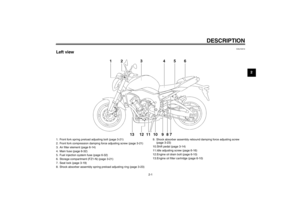 13
13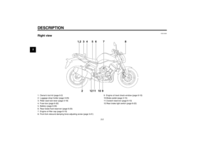 14
14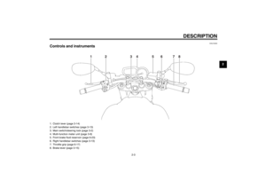 15
15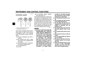 16
16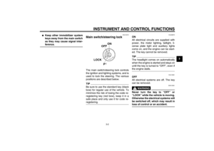 17
17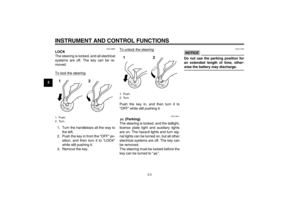 18
18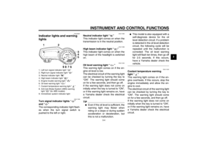 19
19 20
20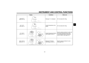 21
21 22
22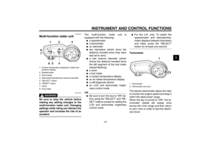 23
23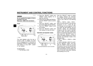 24
24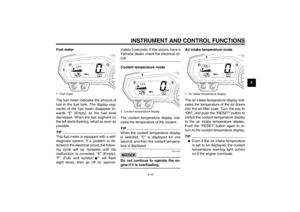 25
25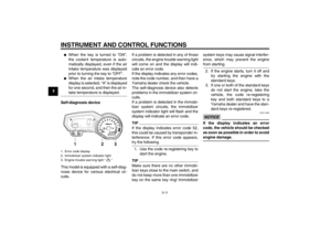 26
26 27
27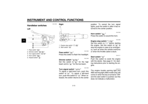 28
28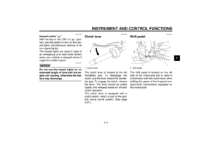 29
29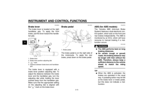 30
30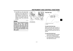 31
31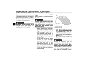 32
32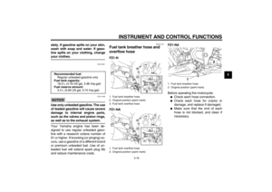 33
33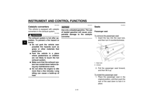 34
34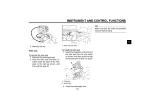 35
35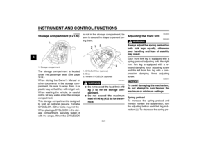 36
36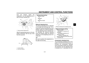 37
37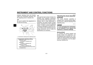 38
38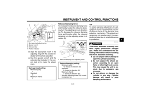 39
39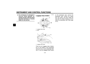 40
40 41
41 42
42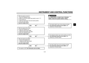 43
43 44
44 45
45 46
46 47
47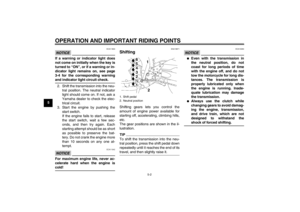 48
48 49
49 50
50 51
51 52
52 53
53 54
54 55
55 56
56 57
57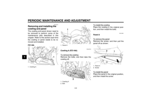 58
58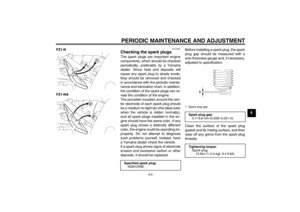 59
59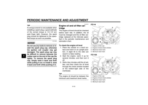 60
60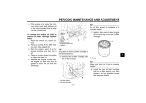 61
61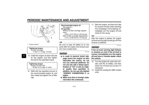 62
62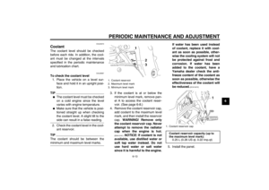 63
63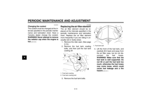 64
64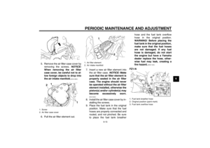 65
65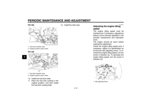 66
66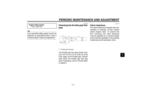 67
67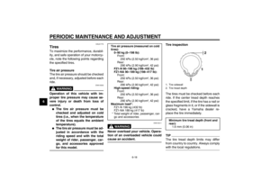 68
68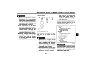 69
69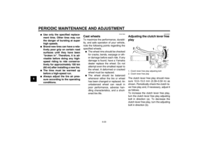 70
70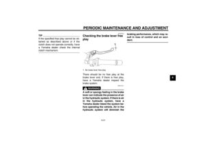 71
71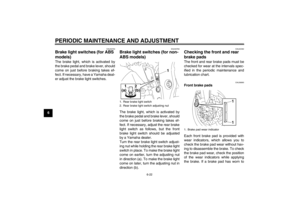 72
72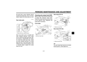 73
73 74
74 75
75 76
76 77
77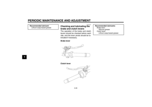 78
78 79
79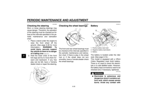 80
80 81
81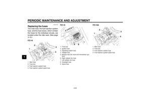 82
82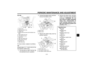 83
83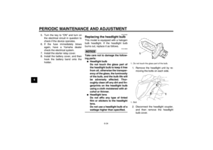 84
84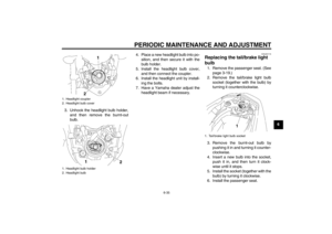 85
85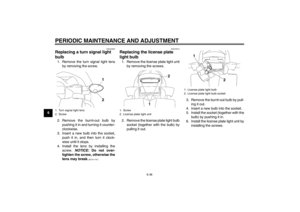 86
86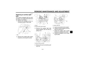 87
87 88
88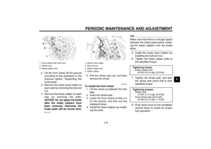 89
89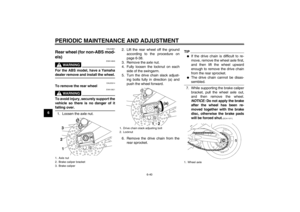 90
90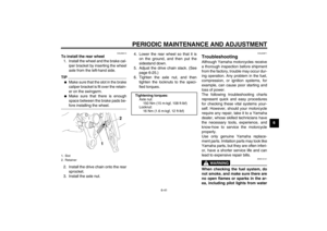 91
91 92
92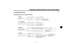 93
93 94
94 95
95 96
96 97
97 98
98 99
99 100
100 101
101 102
102 103
103 104
104 105
105

