Page 319 of 400

08 Maintenance and service
Engine compartment
08
317
For capacities and for standards regarding
water quality, see page 361.
Check the coolant regularlyThe level must lie between the MIN and MAX
marks on the expansion tank. If the system is
not filled sufficiently, high temperatures could
occur, causing a risk of damage to the engine.
IMPORTANT
•A high content of chlorine, chlorides
and other salts may cause corrosion in
the cooling system.
•Always use coolant with anti-corrosion
agent as recommended by Volvo.
•Ensure that the coolant mixture is 50%
water and 50% coolant.
•Mix the coolant with approved quality
tap water. In the event of any doubt
about water quality, used ready-mixed
coolant in accordance with Volvo rec-
ommendations.
•When changing coolant/replacing cool-
ing system components, flush the cool-
ing system clean with approved quality
tap water or flush with ready-mixed
coolant.
•The engine must only be run with a well-
filled cooling system. Otherwise, tem-
peratures that are too high may occur
resulting in the risk of damage (cracks)
in the cylinder head.
Brake and clutch fluid
Checking the levelBrake and clutch fluid have a common reser-
voir. The level must be between the MIN and
MAX marks that are visible inside the reservoir.
Check the level regularly.
Change the brake fluid every other year or at
every other regular service.
For capacities and recommended fluid grade,
see page 361. The fluid should be changed
annually on cars driven in conditions requiring
hard, frequent braking, such as driving in
mountains or tropical climates with high
humidity.
WARNING
If the brake fluid is under the MIN level in the
brake fluid reservoir, do not drive further
before topping up the brake fluid. Volvo rec-
ommends that the reason for the loss of
brake fluid is investigated by an authorised
Volvo workshop.
ProCarManuals.com
Page 320 of 400

08 Maintenance and service
Engine compartment
08
318
Filling
Brake fluid reservoir location.
The fluid reservoir is protected under the cover
over the cold zone in the engine compartment.
The round cover must be removed first before
the reservoir cap can be reached.
1. Turn and open the cover located on the
covering.
2. Unscrew the reservoir cap and fill the fluid.
The level must be between the MIN and
MAX marks, which are located on the
inside of the reservoir.
IMPORTANT
Do not forget to refit the cap.
Power steering fluid
IMPORTANT
Keep the area around the power steering
fluid reservoir clean when checking. The
cover must not be opened.
Check the level frequently. The fluid does not
require changing. The fluid level must be
between the MIN and MAX marks. For capaci-
ties and recommended fluid grade, see
page 361.
NOTE
If a fault should arise in the power steering
system or if the engine is switched off and
the car must be towed, it can still be steered.
ProCarManuals.com
Page 321 of 400

08 Maintenance and service
Lamps
08
319 General
All bulbs are specified, see page 324. The fol-
lowing list contains locations of bulbs and
other light sources that are specialised or
unsuitable for changing except at a workshop:
•Active Xenon headlamps - ABL (Xenon
lamps)
•Direction indicators, door mirrors
•Approach lighting, door mirrors
•Courtesy lighting
•Glovebox lighting
•General interior lighting in the roof
•Reading lamps
•Side position, position lamps rear
•Brake light
•LED lights, general
WARNING
On cars with Xenon headlamps, the
replacement of Xenon lamps must be car-
ried out at a workshop - an authorised Volvo
workshop is recommended. Working with
Xenon lamps demands extreme caution
because the headlamp is equipped with a
high voltage unit.
IMPORTANT
Never touch the glass part of the bulbs with
your fingers. Grease and oils from your fin-
gers are vaporised by the heat, coating the
reflector and then causing damage.
Headlamps front
All of the headlamp bulbs are replaced via the
engine compartment. Loosen and remove the
whole headlamp.
WARNING
The remote control key must not be turned
to key position I or II during bulb replace-
ment.
See the section "Key positions" - for a
description of the remote control key's 3 key
positions.
Removing the headlamp1. Make sure the remote control key is in key
position 0, see page 80:
2. (First illustration)
ProCarManuals.com
Page 322 of 400

08 Maintenance and service
Lamps
08
320
Pull out the headlamp's locking pins.
Release the headlamp by alternately
tilting and pulling it out.
IMPORTANT
Do not pull the electrical cable, only the con-
nector.
3. (Second illustration)
Detach the headlamp connector by
pressing down the clip with your thumb.
At the same time, guide out the con-
nector with your other hand.
4. Lift out the headlamp and place it on a soft
surface to avoid scratching the lens.
5. Replace the bulb in question.
Securing the headlamp
1. Plug in the connector, a clicking sound
should be heard.
2. Reinstall the headlamp and locking pins.
The short pin is fitted closest to the grille.
Check that they are correctly inserted.
3. Check the lighting.
The headlamp must be mounted and the con-
nector correctly installed before the lighting is
switched on or the remote control key is
inserted into the ignition switch.
Removing the cover
Before starting to replace a bulb, see
page 319.
1. Unscrew the cover's four screws with the
tool (1) in the tool kit, see page 294. They
should not be detached completely.
(3 - 4 turns are sufficient.)
IMPORTANT
Use the tool in the toolkit to remove and
attach this correctly.
2. Slide the cover to one side.
3. Remove the cover.
Reinstall the cover in reverse order.
ProCarManuals.com
Page 323 of 400

08 Maintenance and service
Lamps
08
��
* Option/accessory, for more information, see Introduction.321 Dipped beam, halogen
1. Detach the headlamp, see page 319.
2. Remove the cover.
3. Unplug the connector from the bulb.
4. Detach the bulb by pulling it straight out.
5. The guide pin on the lamp should be
straight up when it is fitted and a clicking
sound should be heard when it clicks into
place.
Reinstall the parts in reverse order.
Main beam, Halogen
1. Detach the headlamp.
2. Remove the cover, see page 320
3. Detach the bulb by turning anticlockwise
and then pulling straight out
4. Unplug the connector from the bulb.
5. Replace the bulb and align it in the socket
and turn clockwise in order to secure it. It
can be secured in one position.
Reinstall the parts in reverse order.
Extra main beam, ABL headlamps*
1. Detach the headlamp.
2. Remove the cover, see page 320.
3. Detach the bulb by turning anticlockwise
and then pulling straight out
4. Unplug the connector from the bulb.
5. Replace the bulb and align it in the socket
and turn clockwise in order to secure it. It
can only be secured in one position.
Reinstall the parts in reverse order.
ProCarManuals.com
Page 324 of 400

08 Maintenance and service
Lamps
08
322
Direction indicators/flashers
1. Detach the headlamp.
2. Detach the cover by pulling it straight out.
3. Pull the bulb holder in order to extract the
bulb.
4. Press and simultaneously turn the bulb to
detach it.
Reinstall the parts in reverse order.
Lamp housing, rear
The reversing, fog and direction indicator bulbs
in the rear lamp cluster are replaced from inside
the cargo area.
1. Open the panel.
2. Remove the insulation that is fitted in front
of the bulb holder by pulling it straight out.
3. Press down the catch and pull out the bulb
holder.
4. Remove the blown bulb by pressing it in
and turning anticlockwise.
5. Fit a new bulb, press down and turn clock-
wise.
6. Press down the catch when the bulb holder
is refitted.7. Refit the insulation and panel.
NOTE
If an error message remains after the broken
bulb has been replaced then we recom-
mend that you visit an authorised Volvo
workshop.
Location of rear bulbs
Lamp lens, right-hand side
Brake light (LED)
Direction indicators
Reversing lamp
Rear fog lamp (driver's side)
ProCarManuals.com
Page 325 of 400
08 Maintenance and service
Lamps
08
��
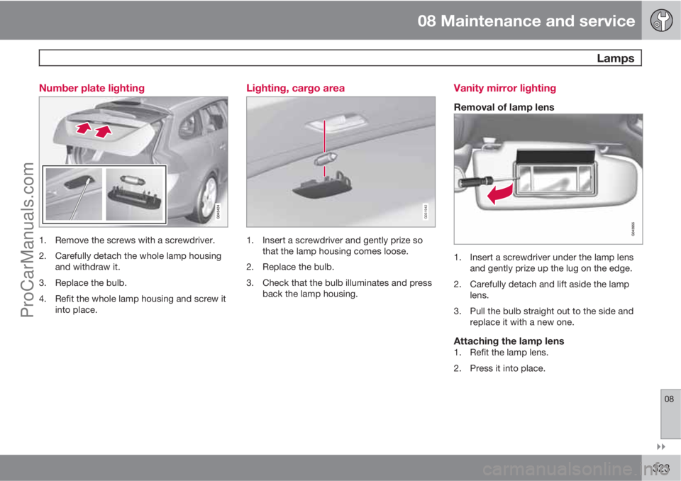
323 Number plate lighting
1. Remove the screws with a screwdriver.
2. Carefully detach the whole lamp housing
and withdraw it.
3. Replace the bulb.
4. Refit the whole lamp housing and screw it
into place.
Lighting, cargo area
G031942
1. Insert a screwdriver and gently prize so
that the lamp housing comes loose.
2. Replace the bulb.
3. Check that the bulb illuminates and press
back the lamp housing.
Vanity mirror lighting
Removal of lamp lens
1. Insert a screwdriver under the lamp lens
and gently prize up the lug on the edge.
2. Carefully detach and lift aside the lamp
lens.
3. Pull the bulb straight out to the side and
replace it with a new one.
Attaching the lamp lens1. Refit the lamp lens.
2. Press it into place.
ProCarManuals.com
Page 326 of 400
08 Maintenance and service
Lamps
08
324
Specification, bulbs
LightingWAType
Dipped beam,
halogen55H7 LL
Main beam,
Halogen65H9
Extra main
beam, ABL65H9
Front direction
indicators21HY21W
Courtesy light-
ing front3T10 Socket
W2.1x9.5d
Glovebox light-
ing5Socket SV8.5
Length 43 mm
Vanity mirror
lighting1.2T5 Socket
W2x4.6d
Cargo area
lighting10Socket SV8.5
Length 43 mm
Number plate
lighting5C5W LL
Direction indi-
cators, rear21PY21W SV
---
LightingWAType
Reversing lamp21P21W LL
Rear fog lamp21H21W LL
AWatt
ProCarManuals.com