2012 VOLKSWAGEN TRANSPORTER tailgate
[x] Cancel search: tailgatePage 193 of 486
@ Kitchen unit with:
-Gas cooker ................................... . 233
242
242
-230-volt grounded safety socket ................. .
-12-volt socket .............................•..................................
-Cupboard with two sliding doors
-Drawer
-Waste water tank with drain lever and opening for cleaning ...... . 237
-First aid kit on the rear panel of the left stowage compartment in the cupboard
@ Refrigerator box ...
@ Wardrobe with:
241
-Cleaning opening for fresh water tank . . . . . . . . . . . . . . . . . . . . . . . . . . . . . . . . . . . . . . . 237
-Second additional battery . . . . . ........ , . . . . . . . . . . . . . . . . . . . . . . . . . . 248
-Lockable stowage compartment . . . . . . . . . . . . . . . . . . . . . . . . . . . . . . . . . . . . . . . . . . . . . . . . 214
@ Stowage area with:
-Residual current circuit breaker ............... , ...... . 247
233
229
-Gas bottle holder .................. .
® Tailgate with room for stowing two camping chairs
Number of seats
The vehicle has a total of 4 seats: 2 at the front and 2 at the rear. Each seat is equipped with a seat belt.
Retrofitting seats
Additional seats can be retrofitted, provided that the maximum number of seats quoted by the man-ufacturer is not exceeded. For this purpose, seat anchor points should be fitted to the vehicle floor by a specialist workshop in accordance with Volks-wagen AG guidelines.
These additional seats must also have seat belt anchor points and suitable seat belts.
The Volkswagen Commercial Vehicles dealership can provide you with more information on retrofit-ting seats.
Furniture Catches
The flaps and doors are fitted with furniture catch-es to prevent them from opening when the vehicle is in motion.
Seat functions, rear, California
ClJ Introduction
This chapter contains information on the following subjects:
Bench seat/bed . . . . . . . . . . . . . . . . . . . . • • . . . 195
Bed (bench seat/bed) . . . . . . . . . . . 196 Mattress, bench seat/bed . . . . . . . . . . . . . . . . . 197
Components of the mattress, 3-seat bench . . 198
To open the doors in the kitchen unit, press and hold the catch. Slide the door open.
Equipment accessible only from the outside of the vehicle
• Opening for filling the fresh water tank on the rear left side of the vehicle (with lockable lid and separate key)
• 230-volt electrical feed on the rear left side of the vehicle (with flap cover)
• Fresh water tank drain opening under the vehi-cle.
• Waste water tank drain opening under the vehi-cle.
• Awning rails on the left and right side of the top of the vehicle on the roof frame.
• Awning adapter on left (if vehicle is fitted with an awning) and on right in the awning rail.
• Awning: attach to aluminium rail on right side over sliding door only.
Mattress for a medium-length bed, 3-seat bench . . . . . . . . . . . . . . . . . . . . . . . . . . . . 199 Mattress for a long bed, 3-seat bench . . . . . . . 201 Stowing the mattress, 3-seat bench . . . . . . . . 203 .,..
Equipment, California 1193
Page 197 of 486
Mattress, bench seat/bed
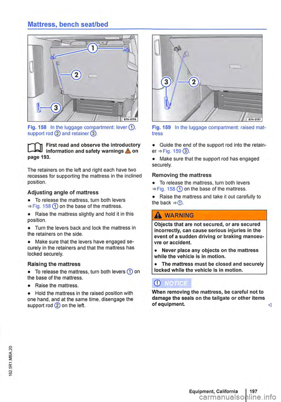
Fig. 158 In the luggage compartment: lever G), support rod @ and retainer@.
r--('n First read and observe the Introductory L.-.J,:.lJ information and safety warnings & on page 193.
The retainers on the left and right each have two recesses for supporting the mattress in the inclined position.
Adjusting angle of mattress
• To release the mattress, turn both levers 158 G) on the base of the mattress.
• Raise the mattress slightly and hold it in this position.
• Turn the levers back and lock the mattress in the retainers on the side.
• Make sure that the levers have engaged se-curely in the retainers and that the mattress has locked securely.
Raising the mattress
• To release the mattress, turn both levers G) on the base of the mattress.
• Raise the mattress.
• Hold the mattress in the raised position with one hand, and at the same time, disengage the support rod@ on the left.
Fig. 159 In the luggage compartment: raised mat-tress
• Guide the end of the support rod into the retain-er 159@.
• Make sure that the support rod has engaged securely.
Removing the mattress
• To release the mattress, turn both levers 158 G) on the base of the mattress.
• Raise the mattress and take it out carefully to the back
A WARNING
Objects that are not secured, or are secured Incorrectly, can cause serious injuries in the event of a sudden driving or braking manoeu-vre or accident.
• Never place any objects on the mattress while the vehicle Is In motion.
• The mattress must be closed and securely locked while the vehicle is In motion.
CD
When removing the mattress, be careful not to damage the seals on the tailgate or other items of equipment.
Page 209 of 486
Interior lights in the living area
OSG.OI12
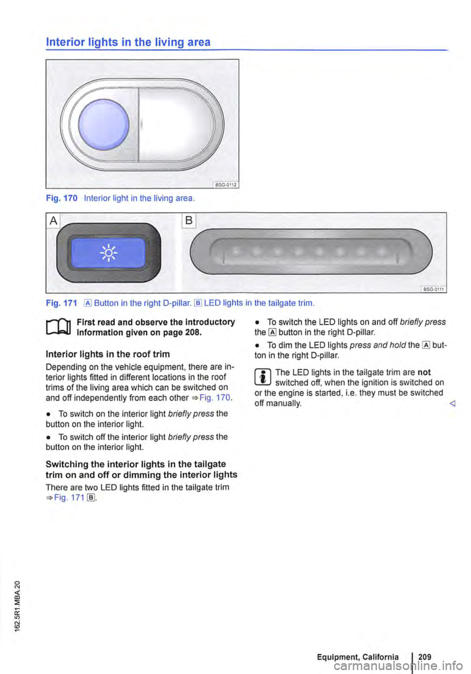
Fig. 170 Interior light in the living area .
.._______)
Fig. 171 [AI Button in the right D-pillar.!ID LED lights in the tailgate trim.
r-1'11 First read and observe the Introductory t.....J,..,lJ Information given on page 208.
Interior lights in the roof trim
Depending on the vehicle equipment, there are in-terior lights fitted in different locations in the roof trims of the living area which can be switched on and off independently from each other 170.
• To switch on the interior light briefly press the button on the interior light.
• To switch off the interior light briefly press the button on the interior light.
Switching the interior lights in the tailgate trim on and off or dimming the interior lights
There are two LED lights fitted in the tailgate trim 171 [ID.
• To switch the LED lights on and off briefly press the [AI button in the right D-pillar.
• To dim the LED lights press and hold the [AI but-ton in the right D-pillar.
m The LED lights in the tailgate trim are not W switched off, when the ignition is switched on or the engine is started, i.e. they must be switched off manually.
Page 213 of 486
Stowage box
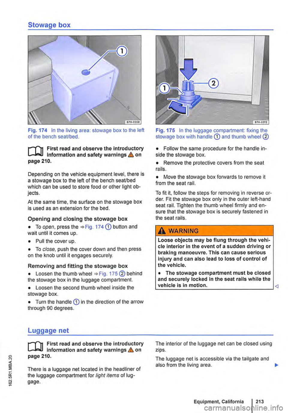
Fig. 174 In the living area: stowage box to the left of the bench seaUbed.
f""'"'('n First read and observe the lntrod uctory L-J,:.,LJ Information and safety warnings & on page 210.
Depending on the vehicle equipment level, there is a stowage box to the left of the bench seaUbed which can be used to store food or other light ob-jects.
At the same time, the surface on the stowage box is used as an extension for the bed.
Opening and closing the stowage box
• To open, press the :;. Fig. 174 (D button and wait until it comes up.
• Pull the cover up.
• To close, push the cover down and then press on the knob until it engages securely.
Removing and fitting the stowage box
• Loosen the thumb wheel :;. Fig. 175 ®behind the stowage box in the luggage compartment.
• Loosen the second thumb wheel inside the stowage box.
• Turn the handle (D in the direction of the arrow through 90 degrees.
Luggage net
f""'"'('n First read and observe the introductory L..-Wl Information and safety warnings & on page 210.
There is a luggage net located in the headliner of the luggage compartment for light items of lug-gage.
Fig. 175 In the luggage compartment: fixing the stowage box with handle
• Remove the protective covers from the seat rails.
• Move the stowage box forwards to remove it from the seat rail.
To fit it, follow the steps for removing in reverse or-der. Fit the stowage box only in the outer left-hand seat rail. Tighten the thumb wheel firmly and en-sure that the stowage box is securely fastened in the seat rails.
A WARNING
Loose objects may be flung through the vehi-cle interior in the event of a sudden driving or braking manoeuvre. This can cause serious injury and can also lead to loss of control of the vehicle.
• The stowage compartment must be closed and securely locked In the seat rails while the vehicle Is In motion.
The luggage net is accessible via the tailgate and also from the living area. .,..
Equipment, California I 213
Page 217 of 486
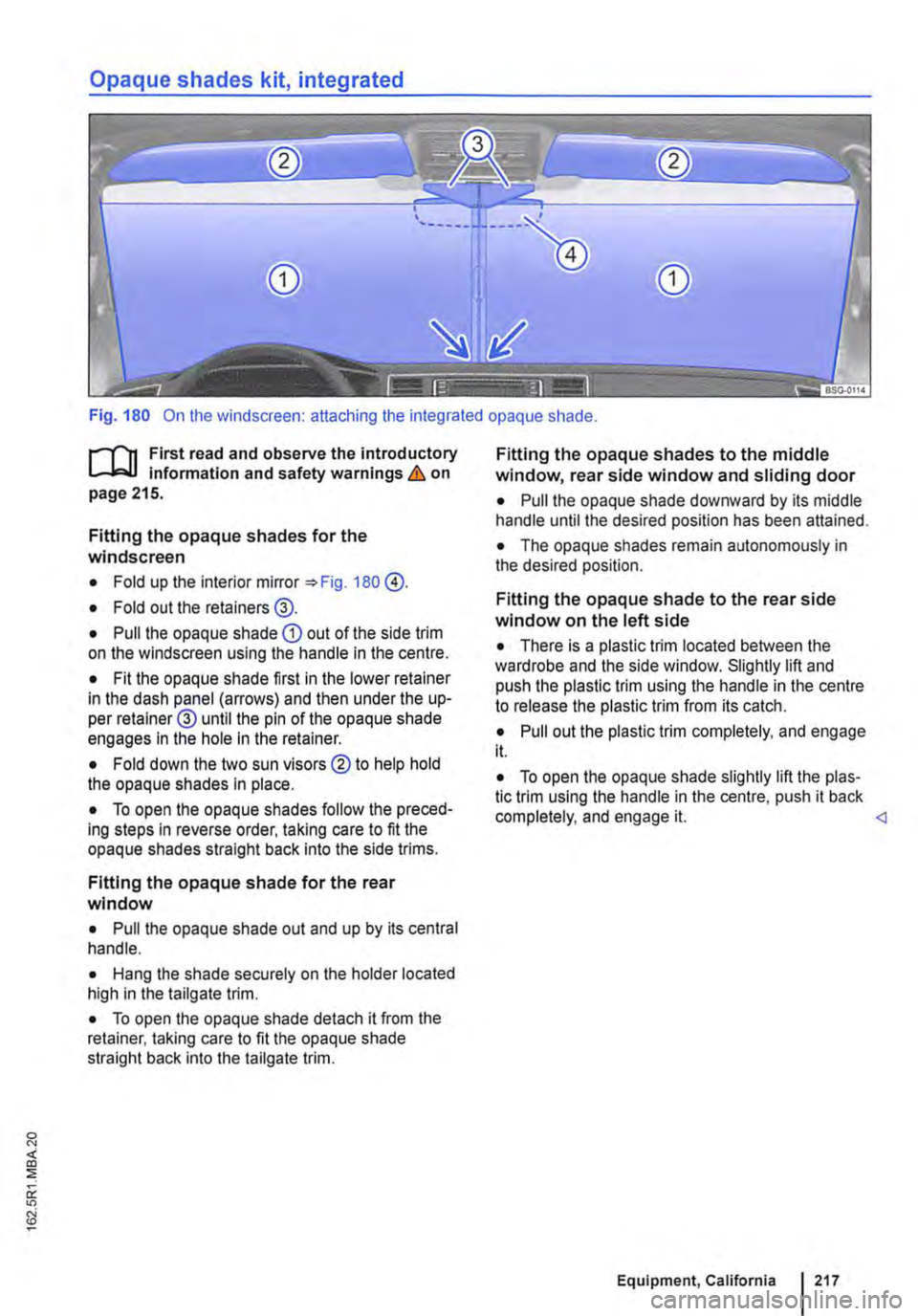
Opaque shades kit, integrated
Fig. 180 On the windscreen: attaching the integrated opaque shade.
f""""'('n First read and observe the introductory L-W.I information and safety warnings & on page 215.
Fitting the opaque shades for the windscreen
• Fold up the interior mirror 180 @.
• Fold out the retainers@.
• Pull the opaque shade CD out of the side trim on the windscreen using the handle in the centre.
• Fit the opaque shade first in the lower retainer in the dash panel (arrows) and then under the up-per retainer@ until the pin of the opaque shade engages In the hole in the retainer.
• Fold down the two sun visors ®to help hold the opaque shades in place.
• To open the opaque shades follow the preced-ing steps in reverse order, taking care to fit the opaque shades straight back Into the side trims.
Fitting the opaque shade for the rear window
• Pull the opaque shade out and up by its central handle.
• Hang the shade securely on the holder located high in the tailgate trim.
• To open the opaque shade detach it from the retainer, taking care to fit the opaque shade straight back into the tailgate trim.
Fitting the opaque shades to the middle window, rear side window and sliding door
• Pull the opaque shade downward by its middle handle until the desired position has been attained.
• The opaque shades remain autonomously in the desired position.
Fitting the opaque shade to the rear side window on the left side
• There is a plastic trim located between the wardrobe and the side window. Slightly lift and push the plastic trim using the handle in the centre to release the plastic trim from its catch.
• Pull out the plastic trim completely, and engage it.
• To open the opaque shade slightly lift the plas-tic trim using the handle in the centre, push it back completely, and engage it.
Page 229 of 486
Tables and camping chairs, California
CllJ Introduction
This chapter contains information on the following subjects:
Folding table in the sliding door . . . . . . . . . . . . 229
Folding the work table out and in . . . . . . . . . . 230
Moving the work table . . . . . . . . . . . . . . . . . • . 231
Camping chairs . . . . . . . . . . . . . . . . . . . . . . . . 232 Flyscreen element for the sliding window . . . . 232
Additional Information and warnings:
• Seat functions, front 69
• Seat functions, rear =>page 72
• Stowage 150
• Stowage areas, California 210
• Drink holder 153
• Tailgate 36
• Awning 226
Folding table in the sliding door
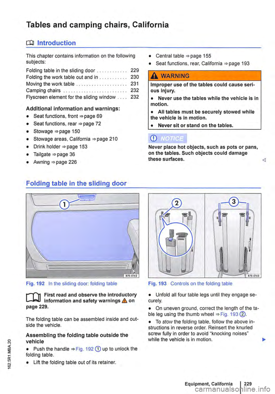
Fig. 192 in the sliding door: folding table
J"'"'"('n First read and observe the introductory L-Jo:.LI information and safety warnings & on page 229.
The folding table can be assembled inside and out-side the vehicle.
Assembling the folding table outside the vehicle
• Push the handle 192 G) up to unlock the folding table.
• Lift the folding table out of its retainer.
• Central table 155
• Seat functions, rear, California 193
,A WARNING
Improper use of the tables could cause seri-ous Injury.
• Never use the tables while the vehicle is in motion.
• All tables must be securely stowed while the vehicle is in motion.
• Never sit or stand on the tables.
CD
Never place hot objects, such as pots or pans, on the tables. Such objects could damage these surfaces.
I !! I
I
I
.. -17£.0161
Fig. 193 Controls on the folding table
• Unfold all four table legs until they engage se-curely.
• On uneven ground, correct the length of theta-ble leg using the thumb wheel 193 @.
• To stow the folding table, follow the above in-structions in reverse order. Reinsert the knurled screw fully in order to avoid "knocking noises" while the vehicle is in motion. .,.
Equipment, California 229
Page 232 of 486
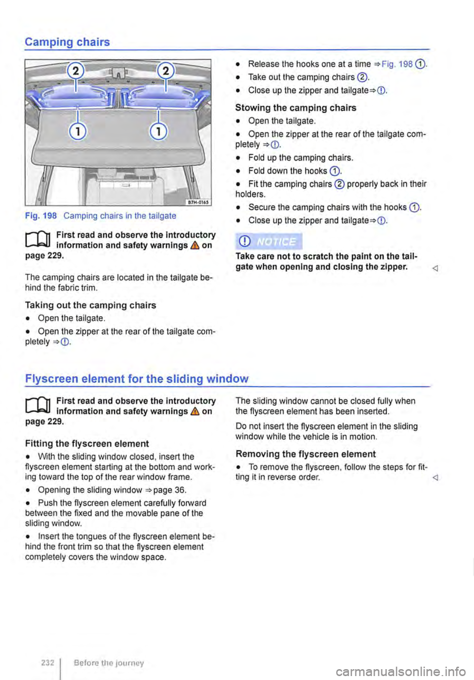
Fig. 198 Camping chairs in the tailgate
r-111 First read and observe the Introductory l.-.lo::.U Information and safety warnings & on page 229.
The camping chairs are located in the tailgate be-hind the fabric trim.
Taking out the camping chairs
• Open the tailgate.
• Open the zipper at the rear of the tailgate com-pletely
• Release the hooks one at a time 198 (}).
• Take out the camping chairs@.
• Close up the zipper and
Stowing the camping chairs
• Open the tailgate.
• Open the zipper at the rear of the tailgate com-pletely
• Fold up the camping chairs.
• Fold down the hooks(}).
• Fit the camping chairs ® properly back in their holders.
• Secure the camping chairs with the hooks (}).
• Close up the zipper and
CD
Take care not to scratch the paint on the tall-gate when opening and closing the zipper.
r-111 First read and observe the introductory l.-.lo::.U Information and safety warnings & on page 229.
Fitting the flyscreen element
• With the sliding window closed, insert the flyscreen element starting at the bottom and work-ing toward the top of the rear window frame.
• Opening the sliding window 36.
• Push the flyscreen element carefully forward between the fixed and the movable pane of the sliding window.
• Insert the tongues of the flyscreen element be-hind the front trim so that the flyscreen element completely covers the window space.
2321 Before tile journey
The sliding window cannot be closed fully when the flyscreen element has been inserted.
Do not insert the flyscreen element in the sliding window white the vehicle is in motion.
Removing the flyscreen element
• To remove the flyscreen, follow the steps for fit-ting it in reverse order.
Page 233 of 486
Gas system, California
c:Q Introduction
This chapter contains information on the following subjects:
Connecting the gas bottle . . . . . . . . . . . . . . . . . 235
Changing the gas bottle . . . . . . . . . . . . . . . 235
Turning the gas cooker on and off . . . . . . . . . . 236
Only butane gas bottles, type 907, manufactured by the company GAZ may be used. The gas bottle must be used in conjunction with a bottle safety valve.
The gas bottle has a sticker on it stating that it is not suitable for use in caravans and camping vehi· cles. This warning means that this gas bottle must not be used unless it Is housed In a special gas bottle compartment.
Notes for vehicles sold in Norway
The gas bottle holder and the gas bottle are de-signed for a 2.0 kg propane gas system. The pres-sure regulator and the propane gas bottle are not connected as shown herein since these parts are retro-fitted by the Volkswagen Commercial Vehi-cles dealership or importer.
Using the gas cooker
• When using the gas cooker for the first time, you may smell gas briefly.
• Open all gas shut-off valves before cooking.
• The pan supports on the gas cooker are merely lodged tightly into place and can be easily re-moved for cleaning.
• Make sure oven mitts and pot holders are dry when handling pots and pans => &.
Energy-efficient usage
For maximum energy efficiency when using the cooker, please follow these suggestions:
• Use pots and pans with a diameter between 16-20cm.
• Use pots and pans with flat (not convex) bot-toms.
• Centre pots and pans over the flame.
• The gas flame should not extend around the edge of the pot or pan.
Additional information:
• Tailgate =>page 36
Leaking gas can cause an explosion.
• If you smell gas when the cooker Is off, take the following actions:
-Ensure there Is no source of fire, spark or open flame in the vicinity.
-Close the safety valve on the gas bottle.
-Open doors and windows to air out the vehicle.
Gas burners use up oxygen in the surround-Ing area. If the vehicle is not ventilated prop-erly, a life threatening lack of oxygen will de-velop.
• Always ensure that there is adequate fresh air entering the vehicle from the mo-ment the gas flame Is lit until it Is turned off again.
• Never use the gas burners to heat the ve-hicle Interior.
A WARNING
Work done improperly on the gas system can lead to serious injury.
• All work on the gas system must be car-ried out by a qualified workshop only.
• Never make modifications to the gas sys-tem.
• If there is a leak or you suspect there is a leak In the gas system, have it checked by a qualified workshop.
A WARNING
Improper or insufficient maintenance of the gas system can compromise its safety and cause serious injury.
• Check the gas hose between the pressure regulator and the gas system regularly. If there Is a leak or you suspect there is a leak In the gas system, have it checked by a quali-fied workshop.
• Have a qualified workshop check the gas system for leaks and proper function every two years. .,.
Equipment, California 233