2012 VOLKSWAGEN TRANSPORTER tow bar
[x] Cancel search: tow barPage 219 of 486
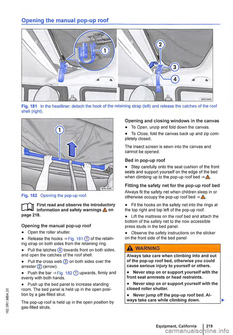
Opening the manual pop-up roof
Fig. 181 In the headliner: detach the hook of the retaining strap (left) and release the catches of the roof shell (right).
Fig. 182 Opening the pop-up roof.
r""'('n First read and observe the introductory L-W.I information and safety warnings & on page 218.
Opening the manual pop-up roof
• Open the roller shutter.
• Release the hooks =>Fig. 181 CD of the retain-ing strap on both sides from the retaining ring.
• Pull the latches @) towards front on both sides, and open the catches of the roof shell.
• Pull the cross web @ on both sides over the arrester® (arrow).
• Push the bar 182 CD upwards, firmly and evenly with both hands.
• Push up the bed panel to increase standing room. The bed panel is held up in the open posi-tion by a gas-filled strut.
The pop-up roof is held up in the open position by gas-filled struts.
Opening and closing windows in the canvas
• To Open, unzip and fold down the canvas.
• To Close, fold the canvas back up and zip com-pletely closed.
The insect screen is sewn into the canvas and cannot be opened.
Bed in pop-up roof
• Step carefully onto the seat cushion of the front seats and support yourself on the edge of the bed when climbing up to the pop-up roof bed => &.
Fitting the safety net for the pop-up roof bed
Always fit the safety net when children sleep in or otherwise occupy the pop-up roof bed => &.
• Fit the hooks on the safety net into the rings at the top right and top left of the pop-up roof.
• Lift the mattress on the roof bed and attach the bottom of the safety net to the now accessible press studs in the bed panel.
• Observe the safety instructions on the sticker on the front side of the bed panel
aAWARNING
Always take care when climbing into and out of the pop-up roof bed, otherwise you could cause serious injury to yourself or others.
• Never step on or support yourself with the front seat armrests or head restraints.
• Never step on or support yourself with the closed roller shutter.
• Never jump off the pop-up roof bed. Al-ways take care while climbing down. Ill>
Equipment, California I 219
Page 220 of 486
A WARNING (Continued)
• Help others, especially children, to climb up and down safely.
A WARNING
If the safety net is not fitted or not properly fitted, children could fall off the pop-up roof bed and seriously injure themselves.
Closing the manual pop-up roof
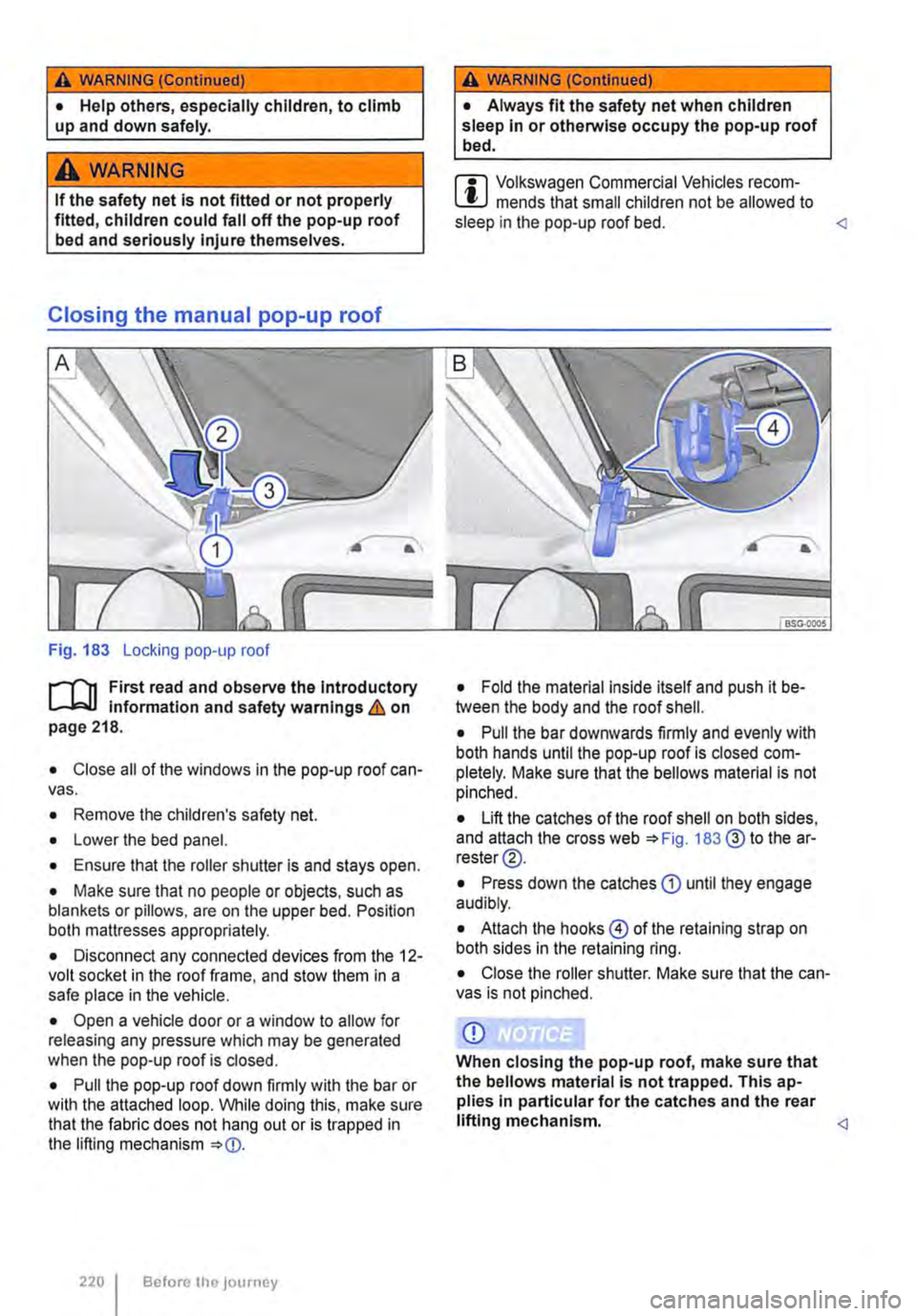
Fig. 183 Locking pop-up roof
,....--('n First read and observe the introductory L-J,::.U information and safety warnings & on page 218.
• Close all of the windows in the pop-up roof can-vas.
• Remove the children's safety net.
• Lower the bed panel.
• Ensure that the roller shutter is and stays open.
• Make sure that no people or objects, such as blankets or pillows, are on the upper bed. Position both mattresses appropriately.
• Disconnect any connected devices from the 12-volt socket in the roof frame, and stow them in a safe place in the vehicle.
• Open a vehicle door or a window to allow for releasing any pressure which may be generated when the pop-up roof is closed.
• Pull the pop-up roof down firmly with the bar or with the attached loop. While doing this, make sure that the fabric does not hang out or is trapped in the lifting mechanism
220 I Before the journey
A WARNING (ConUnued)
• Always fit the safety net when children sleep in or otherwise occupy the pop-up roof bed.
m Volkswagen Commercial Vehicles recom-L!J mends that small children not be allowed to sleep in the pop-up roof bed.
• Pull the bar downwards firmly and evenly with both hands until the pop-up roof is closed com-pletely. Make sure that the bellows material is not pinched.
• Lift the catches of the roof shell on both sides, and attach the cross web 183@ to the ar-rester@.
• Press down the catches CD until they engage audibly.
• Attach the hooks@ of the retaining strap on both sides in the retaining ring.
• Close the roller shutter. Make sure that the can-vas is not pinched.
CD
When closing the pop-up roof, make sure that the bellows material is not trapped. This ap-plies In particular for the catches and the rear lifting mechanism.
Page 235 of 486
Connecting the gas bottle
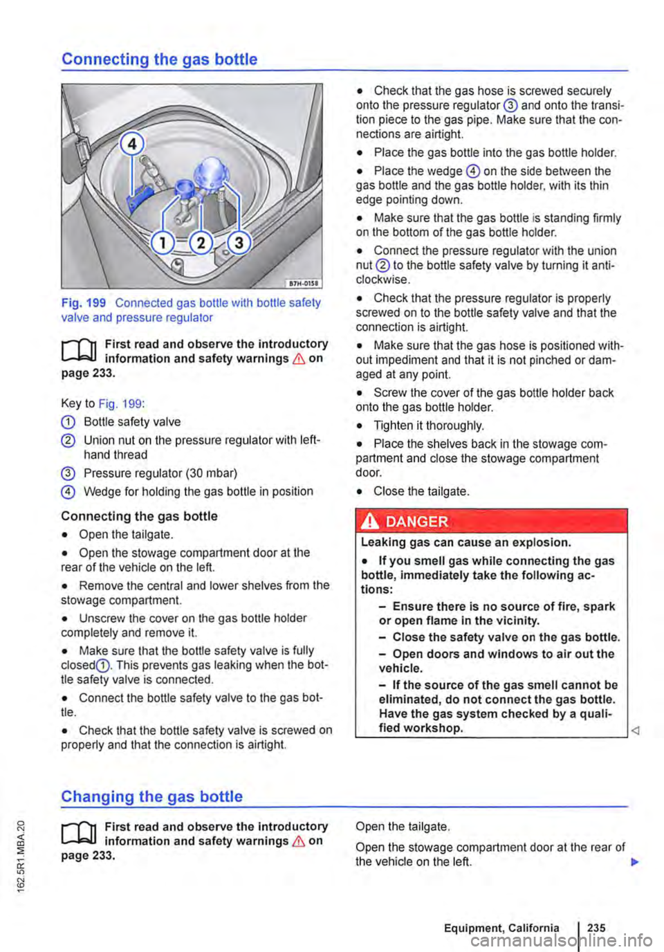
Fig. 199 Connected gas bottle with bottle safety valve and pressure regulator
r-l'n First read and observe the introductory L-J.:.IJ information and safety warnings & on page 233.
Key to Fig. 199:
G) Bottle safety valve
® Union nut on the pressure regulator with left-hand thread
@ Pressure regulator (30 mbar)
@ Wedge for holding the gas bottle in position
Connecting the gas bottle
• Open the tailgate.
• Open the stowage compartment door at the rear of the vehicle on the left.
• Remove the central and lower shelves from the stowage compartment.
• Unscrew the cover on the gas bottle holder completely and remove it.
• Make sure that the bottle safety valve is fully closedG). This prevents gas leaking when the bot-tle safety valve is connected.
• Connect the bottle safety valve to the gas bot-tle.
• Check that the bottle safety valve is screwed on properly and that the connection is airtight.
Changing the gas bottle
r-l'n First read and observe the Introductory L-J.:.IJ information and safety warnings & on page 233.
• Check that the gas hose is screwed securely onto the pressure regulator@ and onto the transi-tion piece to the gas pipe. Make sure that the con-nections are airtight.
• Place the gas bottle into the gas bottle holder.
• Place the wedge @ on the side between the gas bottle and the gas bottle holder. with its thin edge pointing down.
• Make sure that the gas bottle is standing firmly on the bottom of the gas bottle holder.
• Connect the pressure regulator with the union nut® to the bottle safety valve by turning it anti-clockwise.
• Check that the pressure regulator is properly screwed on to the bottle safety valve and that the connection is airtight.
• Make sure that the gas hose is positioned with-out impediment and that it is not pinched or dam-aged at any point.
• Screw the cover of the gas bottle holder back onto the gas bottle holder.
• Tighten it thoroughly.
• Place the shelves back in the stowage com-partment and close the stowage compartment door.
• Close the tailgate.
· &' DANGER .. --' • ,.,_.._.. '·-• I Leaking gas can cause an explosion.
• If you smell gas while connecting the gas bottle, immediately take the following ac-tions:
-Ensure there is no source of fire, spark or open flame in the vicinity.
-Close the safety valve on the gas bottle.
-Open doors and windows to air out the vehicle.
-If the source of the gas smell cannot be eliminated, do not connect the gas bottle. Have the gas system checked by a quali-fied workshop.
Open the stowage compartment door at the rear of the vehicle on the left. 11>
Equipment, California I 235
Page 312 of 486

System limits
r-('n First read and observe the Introductory L-J,:.U Information and safety warnings & on page 307.
The area monitoring system (Front Assist) has physical and system-related limits. The driver may therefore feel that, in certain circumstances, some Front Assist reactions occur unexpectedly or with a delay. You should therefore always be prepared to take full control of the vehicle if necessary.
The following conditions can prevent Front Assist from reacting, or cause a delay in its reaction:
• In tight bends.
• If the accelerator is fully depressed.
• If Front Assist is switched off or there is a fault.
• If TCS or ESC is switched off manually.
• If the ESC is taking corrective action.
• If there is a fault in several brake lights on the vehicle or on a trailer with an electrical connection to the vehicle.
• If the radar sensor is dirty or covered.
• If the vehicle is reversing.
• Under hard acceleration.
• In snow or heavy rain.
• In case of narrow vehicles, e.g. motorbikes.
• If vehicles are travelling slightly to the left or right of your vehicle.
• If vehicles are crossing in front of your vehicle.
• If there is oncoming traffic.
• In uncertain traffic situations.
• 1/Vhen loads or attachment parts on other vehi-cles protrude to the side, rear or above the normal dimensions of the vehicle.
COJ Introduction
This chapter contains information on the following subjects:
Indicator lamp ... .
Operation ....... .
Driving situations ..........•.............
313
314
315
The lane change assist system (Side As-
sist) provides assistance when checking
for traffic behind the vehicle.
The lane change assist system cannot be switched on if the factory-fitted towing bracket is electrically connected to the trailer. The lane change assist system must be switched off manually for non-fac-tory-fitted towing brackets.
The lane change assist system has been designed for use on surfaced roads only.
Additional information and warnings:
• Exterior views =<>page 5
• Volkswagen information system =<>page 24
• Accessories, modifications, repairs and renewal of parts =<>page 394.
3121 While drivmg
A WARNING
The Intelligent technology of the lane change assist system (Side Assist) cannot change the laws of physics or the system-related ve-hicle limitations. Always take care when us-Ing the lane change assist system as you could otherwise cause accidents or Injuries. The system Is not a substitute for the full concentration of the driver.
• Adapt your speed and distance from the vehicles ahead to suit visibility, weather, road and traffic conditions.
• Your hands should always be on the steer-Ing wheel so that you can steer at any time.
• Pay attention to the visual displays in the exterior mirror housing and in the Instrument cluster display, and respond to the com-mands.
• The lane change assist system may react to special roadside structures, e.g. high or offset crash barriers. This can lead to error warnings. ,..
Page 412 of 486
Making you and your vehicle safe
8S0.00)7
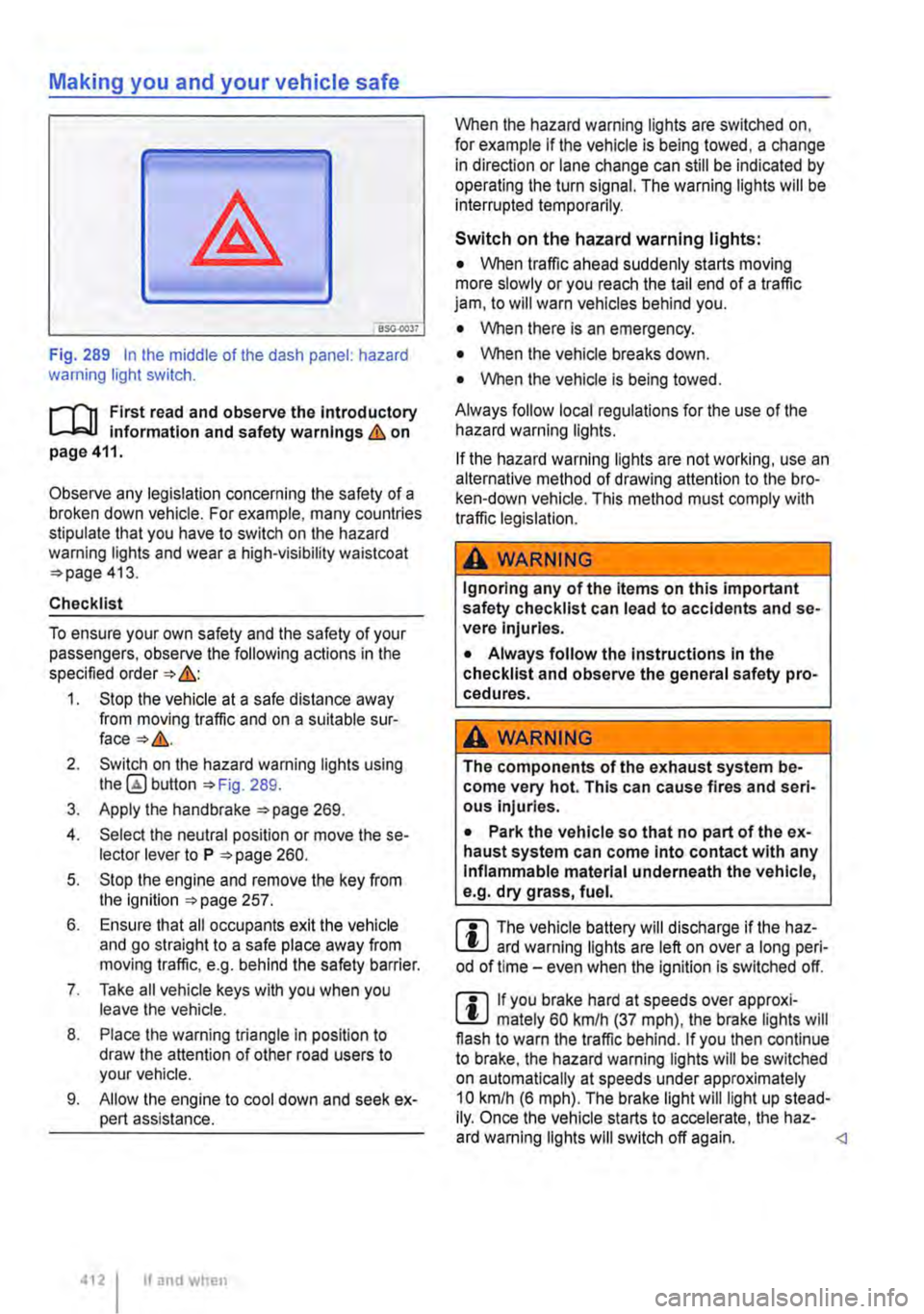
Fig. 289 In the middle of the dash panel: hazard warning light switch.
f"'""'('n First read and observe the Introductory L-lo:.U Information and safety warnings Lb. on page 411.
Observe any legislation concerning the safety of a broken down vehicle. For example, many countries stipulate that you have to switch on the hazard warning lights and wear a high-visibility waistcoat =>page 413.
Checklist
To ensure your own safety and the safety of your passengers, observe the following actions in the specified order => &:
1. Stop the vehicle at a safe distance away from moving traffic and on a suitable sur-face=>&.
2. Switch on the hazard warning lights using button =>Fig. 289.
3. Apply the handbrake =>page 269.
4. Select the neutral position or move the se-lector lever to P =>page 260.
5. Stop the engine and remove the key from the ignition =>page 257.
6. Ensure that all occupants exit the vehicle and go straight to a safe place away from moving traffic, e.g. behind the safety barrier.
7. Take all vehicle keys with you when you leave the vehicle.
8. Place the warning triangle in position to draw the attention of other road users to your vehicle.
9. Allow the engine to cool down and seek ex-pert assistance.
4121 If and when
When the hazard warning lights are switched on, for example if the vehicle is being towed, a change in direction or lane change can still be indicated by operating the turn signal. The warning lights will be interrupted temporarily.
Switch on the hazard warning lights:
• When traffic ahead suddenly starts moving more slowly or you reach the tail end of a traffic jam, to will warn vehicles behind you.
• When there is an emergency.
• When the vehicle breaks down.
• When the vehicle is being towed.
Always follow local regulations for the use of the hazard warning lights.
If the hazard warning lights are not working, use an alternative method of drawing attention to the bro-ken-down vehicle. This method must comply with traffic legislation.
A WARNING
Ignoring any of the items on this important safety checklist can lead to accidents and se-vere Injuries.
• Always follow the Instructions In the checklist and observe the general safety pro-cedures.
A wARNING
The components of the exhaust system be-come very hot. This can cause fires and seri-ous Injuries.
• Park the vehicle so that no part of the ex-haust system can come Into contact with any Inflammable material underneath the vehicle, e.g. dry grass, fuel.
m The vehicle battery will discharge if the haz-L.:!J ard warning lights are left on over a long peri-od of time -even when the Ignition is switched off.
m If you brake hard at speeds over approxi-L.:!J mately 60 km/h (37 mph), the brake lights will flash to warn the traffic behind. If you then continue to brake, the hazard warning lights will be switched on automatically at speeds under approximately 10 km/h (6 mph). The brake light will light up stead-Ily. Once the vehicle starts to accelerate, the haz-ard warning lights will switch off again.
Page 427 of 486
Contents of the breakdown set
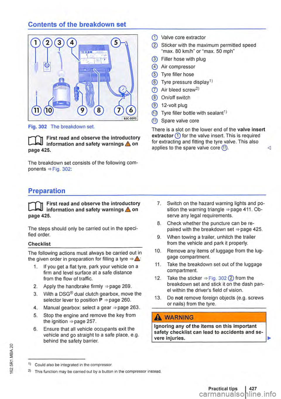
Fig. 302 The breakdown set.
r--T'n First read and observe the introductory L-L::.U information and safety warnings & on page 425.
The breakdown set consists of the following com-ponents 302:
Preparation
r--T'n First read and observe the introductory L-L::.U information and safety warnings & on page 425.
The steps should only be carried out in the speci-fied order.
Checklist
The following actions must always be carried out in the given order in preparation for filling a tyre &:
1. If you get a flat tyre, park your vehicle on a firm and level surface at a safe distance from the flow of traffic.
2. Apply the handbrake firmly 269.
3. With a DSG® dual clutch gearbox, move the selector lever to position P 260.
4. Manual gearbox: select a gear 263.
5. Stop the engine and remove the key from the ignition 257.
6. Ensure that all vehicle occupants exit the vehicle and go straight to a safe place, e.g. behind the safety barrier.
1) Could also be integrated in the compressor.
CD Valve core extractor
® Sticker with the maximum permitted speed "max. 80 km/h" or "max. 50 mph"
@ Filler hose with plug
@ Air compressor
® Tyre filler hose
® Tyre pressure display 1 l
0 Air bleed screw2l
® On/off switch
® 12-volt plug
@ Tyre filler bottle with sealant1l
® Spare valve core
There is a slot on the lower end of the valve insert extractor CD for the valve insert. This is required for extracting and fitting the tyre valve. This also applies to the spare valve core @.
8. Check whether the puncture can be re-paired with the breakdown set 425.
9. When towing a trailer, unhitch the trailer from the vehicle and park it properly.
10. Remove any items of luggage from the lug-gage compartment.
11. Take the breakdown set out of the luggage compartment.
12. Take the sticker 302 ®from the breakdown set and stick it on the dash pan-el within the driver's field of vision.
13. Do not remove foreign objects (e.g. screws or nails) from the tyre.
A WARNING
Ignoring any of the items on this important safety checklist can lead to accidents and se-vere Injuries. ,..
2) This function may be carried out by a button in the compressor instead.
Practical tips 427
Page 428 of 486
A WARNING (Continued)
• Always follow the instructions In the checklist and observe the general safety pro-
Sealing and inflating tyres
r-"'('n First read and observe the Introductory L-J,.:.U Information and safety warnings & on page 425.
Sealing a tyre
• Unscrew the cap from the tyre valve.
• Use the valve core extractor 302 CD to screw the valve core out of the tyre valve. Place the core on a clean surface.
• Shake the tyre filler bottle 302 ® vigo-rously up and down several times.
• Screw the filler hose 302 @tightly onto the tyre filler bottle in a clockwise direction. The plastic foil on the plug is pierced automatically.
• Remove the plug from the filler hose 302@ and place the open end fully on the tyre valve.
• Hold the bottle upside down and inject the en-tire contents of the tyre filler bottle into the tyre.
• Remove the empty tyre filler bottle from the valve.
• Use the valve core extractor 302 CD to screw the valve core back onto the tyre valve.
Inflating the tyre
• Screw the tyre filler hose 302 ® of the air compressor tightly onto the tyre valve.
• Check that the bleed screw 302 (?) is closed.
• Start the engine and let it run.
• Insert the plug 302 ®into one of the ve-hicle's 12-volt sockets 163.
• Use the on/off switch 302 ®to switch on the air compressor.
• Run the compressor until the tyre pressure has reached 2.0-2.5 bar (29-36 psi I 200-250 kPa) maximum running time is 6 minutes
• Switch off the air compressor.
• If a pressure level of 2.0-2.5 bar (29-36 psi I 200 -250 kPa) cannot be achieved unscrew the tyre filler hose from the tyre valve.
428 I If and when
• Drive (or reverse) the vehicle approximately 1 0 metres so that the sealing compound is more evenly distributed in the tyre.
• Screw the tyre filler hose for the air compressor firmly back onto the tyre valve and inflate the tyre again.
• If the required pressure still cannot be reached, the tyre is too badly damaged. The tyre cannot be sealed with the breakdown set. Do not drive on. Seek expert assistance &.
• Disconnect the air compressor and unscrew the tyre filler hose from the tyre valve.
• Drive the vehicle no faster than 80 km/h (50 mph) once a tyre pressure of 2.0-2.5 bar (29-36 psi I 200-250 kPa) has been reached.
• Check the tyre pressure after driving for 10 mi-nutes 429.
A WARNING
The tyre filler hose and the air compressor can get hot during Inflation.
• Protect your hands and skin from the hot components.
• Do not place the hot tyre filler hose or the hot air compressor on any Inflammable mate-rials.
• Allow the device to cool down fully before stowing.
• If the tyre will not Inflate to at least 2.0 bar (29 psi/ 200 kPa), the tyre Is too damaged. The sealant Is unable to seal the tyre. Do not drive on. Seek expert assistance.
CD
Switch the air compressor off after a maximum of 6 minutes to avoid overheating. Let the air compressor cool down for a few minutes be-fore switching it back on.
Page 447 of 486
• Switch on the ignition and the hazard warning lights.
• Once both vehicles are in motion, release the clutch.
• As soon as the engine starts, press the clutch and put the gear into neutral. This helps to prevent driving into the towing vehicle.
Notes on towing
i"""fl1 First read and observe the introductory L-W! information and safety warnings & on page 446.
Fixed towing eye at rear
On vehicles without a towing bracket there is a fixed towing eye under the bumper at the rear right.
Towing bracket instead of a fixed towing eye
If the vehicle has a factory-fitted towing bracket, it should also be used for towing other vehicles.
Tow rope or tow bar
lt is easier and safer to tow a vehicle with a tow bar. Only use a tow rope if you do not have a tow bar.
The tow rope should be slightly elastic to reduce the strain on both vehicles. lt is advisable to use a tow rope made of synthetic fibre or similarly elastic material.
Only attach the tow rope or tow bar to the specially provided towing eyes or to the towing bracket.
Vehicles with a factory-fitted towing bracket must be towed only with a tow bar that is specially designed for fitting to a ball coupling 139.
When your vehicle has to be towed:
• Switch on the ignition.
• Select the neutral position or move the selector lever to N 257.
• Release the handbrake. if necessary.
CD
When tow-starting, unburnt fuel can enter the catalytic converter and damage it. <1
• Do not allow the vehicle to be towed at speeds faster than 50 km/h (30 mph).
• Do not allow the vehicle to be towed further than 50 km.
• Vehicles with a DSG® dual clutch gearbox may only be towed by the breakdown truck with the front wheels raised.
Towing vehicles with four-wheel drive (4MOTION)
Vehicles with four-wheel drive (4MOTION) may be towed with a tow bar or tow rope. If the vehicle is towed with the rear or front axle raised, the engine must be switched off otherwise the drive train could be damaged.
When should your vehicle not be towed?
• If, due to damage, the vehicle gearbox no lon-ger contains any lubricant.
• If the vehicle battery is discharged.
• If the distance to be towed is further than 50 km -applies only to vehicles with the DSG® dual clutch gearbox.
• If the steering function or the operating clear-ance of the wheels cannot be ensured, e.g. after an accident.
Please comply with the following when towing another vehicle:
• Comply with legal regulations.
• Comply with the information on towing con-tained in the owner's manual for the other vehicle. <1
Practical tips