Page 508 of 744
508
3-8. Other interior features
Floor mat
Use only floor mats designed specifically for vehicles of the same
model and model year as your vehicle. Fix them securely in place
onto the carpet.
Insert the retaining hooks
(clips) into the floor mat eye-
lets.
Turn the upper knob of each
retaining hook (clip) to secure
the floor mats in place.
*: Always align the marks.
The shape of the retaining hooks (clips) may differ from that shown in the
illustration.
*
Page 509 of 744

509
3-8. Other interior features
3
Interior and exterior features
CAUTION
Observe the following precautions.
Failure to do so may cause the driver’s floor mat to slip, possibly interfering
with the pedals while driving. An unexpectedly high speed may result or it may
become difficult to stop the vehicle, leading to a serious accident.
■
When installing the driver’s floor mat
●Do not use floor mats designed for other models or different model year
vehicles, even if they are Toyota Genuine floor mats.
● Only use floor mats designed for the driver’s seat.
● Always install the floor mat securely using the retaining hooks (clips) pro-
vided.
● Do not use two or more floor mats on top of each other.
● Do not place the floor mat bottom-side up or upside-down.
■ Before driving
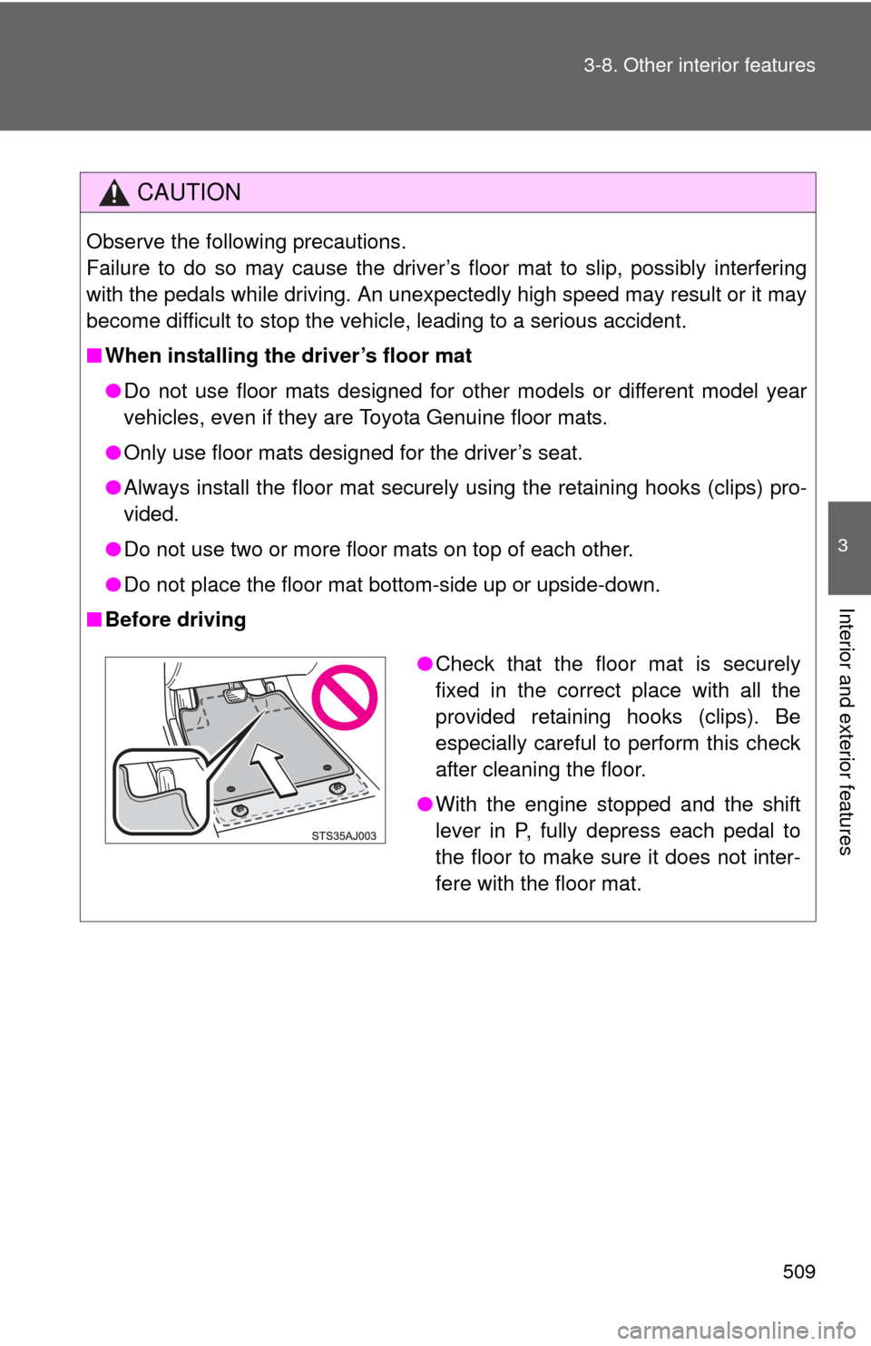
●Check that the floor mat is securely
fixed in the correct place with all the
provided retaining hooks (clips). Be
especially careful to perform this check
after cleaning the floor.
● With the engine stopped and the shift
lever in P, fully depress each pedal to
the floor to make sure it does not inter-
fere with the floor mat.
Page 510 of 744
510
3-8. Other interior features
Luggage compartment features
■Deck hooks
Deck hooks are provided for
securing loose items.
Page 513 of 744
513
3-8. Other interior features
3
Interior and exterior features
Garage door opener
The garage door opener (HomeLink® Universal Transceiver) is manufac-
tured under license from HomeLink®.
Programming the HomeLink® (for U.S.A. owners)
The HomeLink
® compatible transceiver in your vehicle has 3 buttons
which can be programmed to operate 3 different devices. Refer to the
programming method below appropriate for the device.
Indicator
Buttons
: If equipped
The garage door opener can be programmed to operate garage
doors, gates, entry doors, door locks, home lighting systems, secu-
rity systems, and other devices.
Page 516 of 744

516 3-8. Other interior features
Press and hold the vehicle’s programmed HomeLink® button
for 2 seconds and release it. Repeat this step once again. The
garage door may open.
If the garage door opens, the programming process is complete. If
the door does not open, press and release the button a third time.
This third press and release will complete the programming process
by opening the garage door.
The ceiling mounted garage door opener motor should now recog-
nize the HomeLink
® transceiver and operate the garage door.
Repeat the steps above to prog ram another rolling code sys-
tem for any of the remaining HomeLink® buttons.
■ Programming an entry gate (f or U.S.A. owners)/Programming
all devices in the Canadian market
Place your transmitter 1 to 3 in. (25 to 75 mm) away from the
surface of the HomeLink
®.
Keep the indicator on the HomeLink® in view while programming.
Press and hold the selected HomeLink® button.
Repeatedly press and release (cycle) the device’s remote
control button for two seconds each until step 4 is completed.
When the indicator on the HomeLink
® compatible transceiver
start to flashing rapidly, release the buttons.
Test the operation of the HomeLink
® by pressing the newly
programmed button. Check to se e if the gate/device operates
correctly.
Repeat the steps above to program another device for each of
the remaining HomeLink
® buttons.
■ Programming other devices
To program other devices such as home security systems, home
door locks or lighting, contact your authorized Toyota dealer for
assistance.
Page 523 of 744

523
3-8. Other interior features
3
Interior and exterior features
■
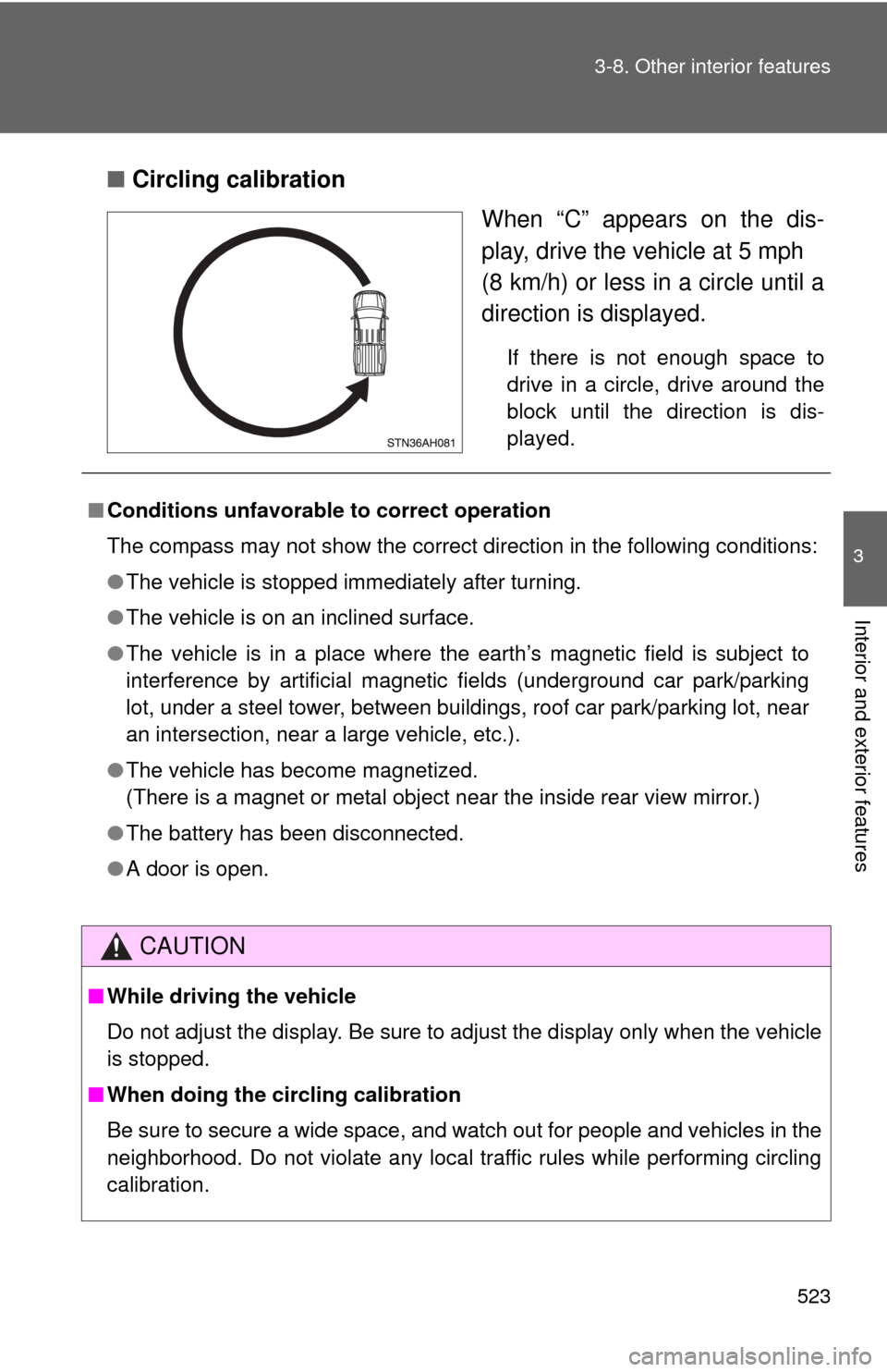
Circling calibration
When “C” appears on the dis-
play, drive the vehicle at 5 mph
(8 km/h) or less in a circle until a
direction is displayed.
If there is not enough space to
drive in a circle, drive around the
block until the direction is dis-
played.
■Conditions unfavorable to correct operation
The compass may not show the correct direction in the following conditions:
●The vehicle is stopped immediately after turning.
● The vehicle is on an inclined surface.
● The vehicle is in a place where the earth’s magnetic field is subject to
interference by artificial magnetic fields (underground car park/parking
lot, under a steel tower, between buildings, roof car park/parking lot, near
an intersection, near a large vehicle, etc.).
● The vehicle has become magnetized.
(There is a magnet or metal object near the inside rear view mirror.)
● The battery has been disconnected.
● A door is open.
CAUTION
■While driving the vehicle
Do not adjust the display. Be sure to adjust the display only when the vehicle
is stopped.
■ When doing the circling calibration
Be sure to secure a wide space, and watch out for people and vehicles in the
neighborhood. Do not violate any local traffic rules while performing circling
calibration.
Page 535 of 744
535
4-2. Maintenance
4
Maintenance and care
Vehicle interior
ItemsCheck points
Accelerator pedal • Moves smoothly (without uneven
pedal effort or catching)?
Automatic transmission “Park”
mechanism • Can the vehicle be held securely
on an incline with the shift lever in
P?
Brake pedal • Moves smoothly?
• Does it have appropriate clear-
ance and correct amount of free
play?
Brakes • Not pull to one side when
applied?
• Loss of brake effectiveness?
• Spongy feeling brake pedal?
• Pedal almost touches floor?
Head restraints • Move smoothly and lock
securely?
Indicators/buzzers • Function properly?
Lights • Do all the lights come on?
• Headlights aimed correctly?
Parking brake • Moves smoothly?
• Can hold the vehicle securely on
an incline?
Seat belts • Does the seat belt system oper-
ate smoothly?
• Are the belts undamaged?
Seats • Do the seat controls operate
properly?
Steering wheel • Moves smoothly?
• Has correct free play?
• No strange noises?
Page 582 of 744

582 4-3. Do-it-yourself maintenance
23 ECU-B17.5 AMultiplex communication system,
Multiport fuel injection system/
sequential multiport fuel injection
system, auto anti-glare inside rear
view mirror, power outlets, power
front driver’s seat, power tilt and
power telescopic
24 DOME 7.5 AInterior lights, personal lights, van-
ity lights, engine switch light, foot
light, accessory meter
25 HEAD LH 15 ALeft-hand headlight
(high beam)
26 HEAD LL 15 ALeft-hand headlight
(low beam)
27 INJ 10 AMultiport fuel injection system/
sequential multiport fuel injection
system, ignition system
28 MET 7.5 A Gauges and meters
29 IGN 10 ASRS airbag system, multiport fuel
injection system/sequential multi-
port fuel injection system, cruise
control system
30 HEAD RH 15 ARight-hand headlight
(high beam)
31 HEAD RL 15 ARight-hand headlight
(low beam)
32 EFI NO.2 10 AMultiport fuel injection system/
sequential multiport fuel injection
system, leak detection pump
33 DEF I/UP 5 A No circuit
34 SPARE 5 A Spare fuse
35 SPARE 15 A Spare fuse
36 SPARE 30 A Spare fuse
FuseAmpereCircuit