Page 558 of 636

558
5-2. Steps to take in an emergency
If the electronic key does not operate properly (vehicles with smart key system)
Locking and unlocking the doors, and mechanical key linked functions
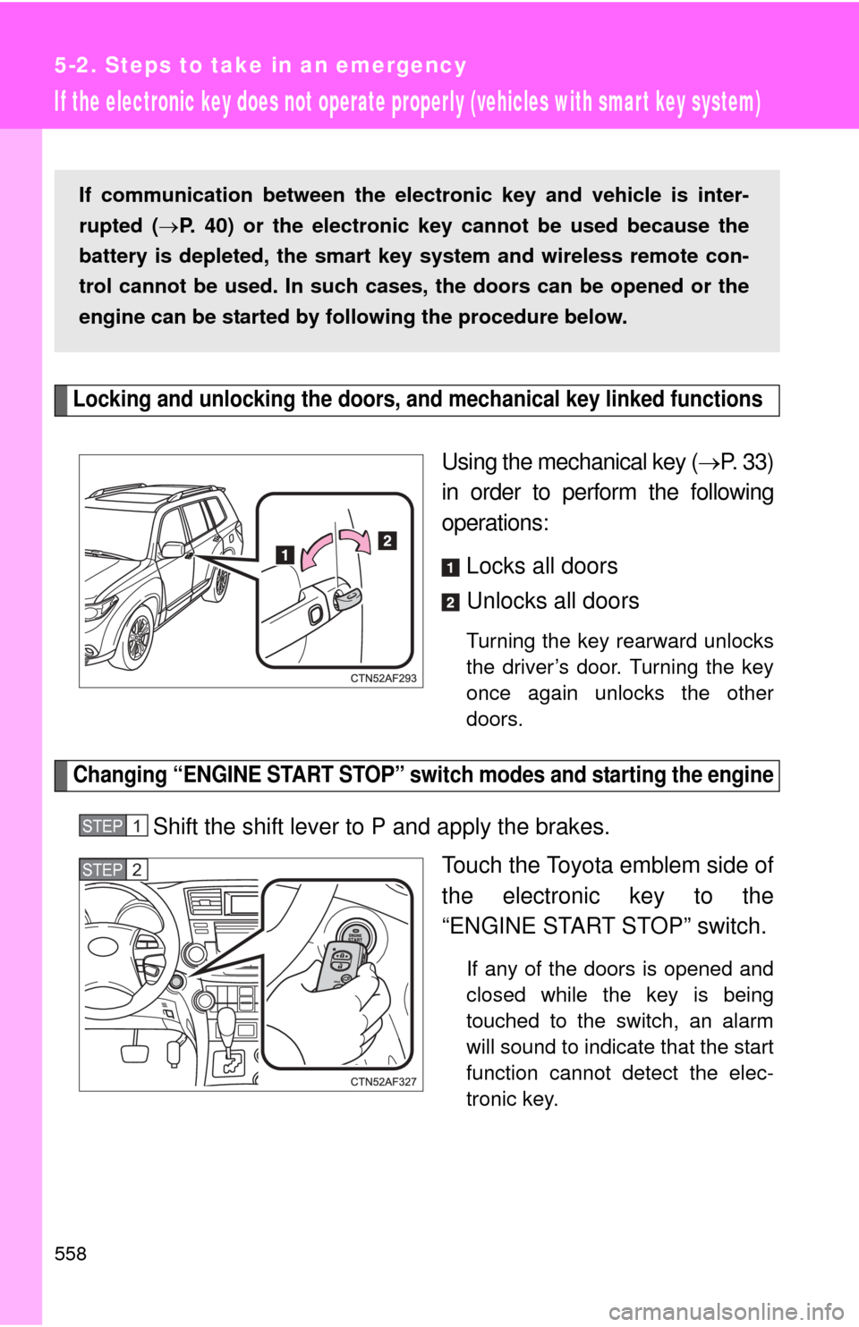
Using the mechanical key (P. 33)
in order to perform the following
operations:
Locks all doors
Unlocks all doors
Turning the key rearward unlocks
the driver’s door. Turning the key
once again unlocks the other
doors.
Changing “ENGINE START STOP” switch modes and starting the engine
Shift the shift lever to P and apply the brakes. Touch the Toyota emblem side of
the electronic key to the
“ENGINE START STOP” switch.
If any of the doors is opened and
closed while the key is being
touched to the switch, an alarm
will sound to indicate that the start
function cannot detect the elec-
tronic key.
If communication between the electronic key and vehicle is inter-
rupted (P. 40) or the electronic key cannot be used because the
battery is depleted, the smart key system and wireless remote con-
trol cannot be used. In such cases, the doors can be opened or the
engine can be started by following the procedure below.
STEP1
STEP2
Page 559 of 636
5
When trouble arises
559
5-2. Steps to take in an emergency
To change “ENGINE START STOP” switch modes: Within 5
seconds of the buzzer soundin
g, release the brake pedal and
press the “ENGINE START STOP” switch. Modes can be
changed each time the sw itch is pressed. (P. 171)
To start the engine: Press the “ENGINE START STOP” switch
within 5 seconds after the buzz er sounds, keeping the brake
pedal depressed.
In the event that the “ENGINE ST ART STOP” switch still cannot be
operated, contact your Toyota dealer.
■ Stopping the engine
Shift the shift lever to P and press the “ENGINE START STOP” switch as
you normally do when stopping the engine.
■ Replacing the electronic key battery
As the above procedure is a temporary measure, it is recommended that the
electronic key battery be replaced immediately when the battery depletes.
(P. 497)
STEP3
Page 560 of 636
560
5-2. Steps to take in an emergency
If the batter y is discharged
The following procedures may be used to start the engine if the vehi-
cle's battery is discharged.
You can call your Toyota dealer or qualified repair shop.
If you have a set of jumper (or boo ster) cables and a second vehi-
cle with a 12-volt battery, you can jump start your Toyota following
the steps below.
Connect the jumper cables.
2.7 L 4-cylinder (1AR-FE) engine
STEP1
Page 561 of 636
5
When trouble arises
561
5-2. Steps to take in an emergency
3.5 L V6 (2GR-FE) engine
Positive (+) battery terminal on your vehicle
Positive (+) battery terminal on the second vehicle
Negative (-) battery terminal on the second vehicle
Connect the jumper cable to ground on your vehicle as shown in
the illustration.
Start the engine of the second vehicle. Increase the engine
speed slightly and maintain at that level for approximately 5
minutes to recharge the battery of your vehicle.
Vehicles with smart key system:
Open and close any of the doors with the “ENGINE START
STOP” switch OFF.
STEP2
STEP3
Page 562 of 636

562 5-2. Steps to take in an emergency
■Starting the engine when the battery is discharged
The engine cannot be started by push-starting.
■ To prevent battery discharge
●Turn off the headlights and the audio system while the engine is turned
off.
● Turn off any unnecessary electrical components when the vehicle is run-
ning at a low speed for an extended period, such as in heavy traffic, etc.
■ When the battery is removed or discharged
●The power back door must be initialized ( P. 6 4 )
● The tire inflation pressure warning system must be initialized. ( P. 480)
■ Charging the battery
The electricity stored in the battery will discharge gradually even when the
vehicle is not in use, due to natural discharge and the draining effects of cer-
tain electrical appliances. If the vehicle is left for a long time, the battery may
discharge, and the engine may be unable to start. (The battery recharges
automatically during driving.)
Vehicles without smart key system:
Maintain the engine speed of the second vehicle, and turn
the engine switch to the “ON” position, then start the vehi-
cle's engine.
Vehicles with smart key system:
Maintain the engine speed of the second vehicle, and turn
the “ENGINE START STOP” switch to IGNITION ON mode,
then start the vehicle's engine.
Once the vehicle’s engine has started, remove the jumper
cables in the exact reverse order in which they were con-
nected.
Once the engine starts, have the vehicle checked at your Toyota
dealer as soon as possible.STEP4
STEP5
Page 563 of 636

5
When trouble arises
563
5-2. Steps to take in an emergency
CAUTION
■
Avoiding battery fires or explosions
Observe the following precautions to prevent accidentally igniting the flam-
mable gas that may be emitted from the battery.
●Make sure the jumper cable is connected to the correct terminal and that it
is not unintentionally in contact with any part other than the intended termi-
nal.
● Do not allow the + and - clamps of the jumper cables to come into contact
with each other.
● Do not smoke, use matches, cigarette lighters or allow open flame near
the battery.
■ Battery precautions
The battery contains poisonous and corrosive acidic electrolyte, while
related parts contain lead and lead compounds. Observe the following pre-
cautions when handling the battery.
●When working with the battery, always wear safety glasses and take care
not to allow any battery fluids (acid) to come into contact with skin, clothing
or the vehicle body.
● Do not lean over the battery.
● In the event that battery fluid comes into contact with the skin or eyes,
immediately wash the affected area with water and seek medical attention.
Place a wet sponge or cloth over the affected area until medical attention
can be received.
● Always wash your hands after handling the battery support, terminals, and
other battery-related parts.
● Do not allow children near the battery.
NOTICE
■When handling jumper cables
Be careful that the jumper cables do not become tangled in the cooling fan
or any of the belts when connecting or disconnecting them.
Page 581 of 636
581
6-1. Specifications
6
Vehicle specifications
Ignition system
Electrical system
Spark plug
Make
Gap
2.7 L 4-cylinder (1AR-FE) engine
DENSO, SK16HR11
3.5 L V6 (2GR-FE) engine
DENSO FK20HR11
0.043 in. (1.1 mm)
NOTICE
■ Iridium-tipped spark plugs
Use only iridium-tipped spark plugs. Do not adjust gap when tuning engine.
Battery
Open voltage* at
68 F (20 C): 12.6 12.8 V Fully charged
12.2 12.4 V Half charged
11 . 8
12.0 V Discharged
(*: Voltage is checked 20 minutes after the engine
and all the lights are turned off)
Charging rates 5 A max.
Page 597 of 636

597
6-1. Specifications
6
Vehicle specifications
Tire related termMeaning
Normal occupant
weight 150 lb. (68 kg) times the number of occupants
specified in the second column of Table 1
* that
follows
Occupant distribution Distribution of occupants in a vehicle as speci-
fied in the third column of Table 1
* below
Production options
weight The combined weight of installed regular pro-
duction options weighing over 5 lb. (2.3 kg) in
excess of the standard items which they
replace, not previously considered in curb
weight or accessory weight, including heavy
duty brakes, ride levelers, roof rack, heavy duty
12-volt battery, and special trim
Rim A metal support for a tire or a tire and tube
assembly upon which the tire beads are seated
Rim diameter
(Wheel diameter) Nominal diameter of the bead seat
Rim size designation Rim diameter and width
Rim type designation The industry manufacturer's designation for a
rim by style or code
Rim width Nominal distance between rim flanges
Vehicle capacity
weight (Total load
capacity) The rated cargo and luggage load plus 150 lb.
(68 kg) times the vehicl
e's designated seating
capacity
Vehicle maximum load
on the tire The load on an individual tire that is determined
by distributing to each axle its share of the
maximum loaded vehicle weight, and dividing
by two
Vehicle normal load
on the tire The load on an individual tire that is determined
by distributing to each axle its share of curb
weight, accessory weight, and normal occu-
pant weight (distributed in accordance with
Ta b l e 1
* below), and dividing by two