Page 3 of 240

iii
Important information about your
To y o t a
Accessories, spare parts and
modification of your Toyota
Both genuine Toyota and a wide variety of other spare parts and
accessories for Toyota vehicles are currently available on the market.
Should it be determined that any of the genuine Toyota parts or
accessories supplied with the vehicle need to be replaced, Toyota
recommends that genuine Toyota parts or accessories, be used to
replace them. Other parts or accessories of matching quality can
also be used. Toyota cannot acceptany liability orguarantee spare
parts and accessories which are not genuine Toyota products, nor for
replacement or installation involving such parts. In addition, damage
or performance problems resulting from the use of non−genuine
Toyota spare parts or accessories may not be covered under
warranty.
Installation of an RF−transmitter system
As the installation of an RF−transmitter system in your vehicle could
affect electronic systems such as the electronically controlled fuel
pump, electronic engine controlsystem, anti−lock brake system, SRS
airbag system and seat belt pretensionersystem, be sure to check
with any authorized Toyota dealer or repairer, or another duly quali-
fied and equipped professional, for precautionary measures or special
instructions regarding installation.
Further information regarding frequency bands, power levels, antenna
positions and installation provisions for the installation of RF−trans-
mitters, is available on request at any authorized Toyota dealer or
repairer, or another duly qualified and equipped professional.
Dyna100/150_EE
Page 12 of 240
6OVERVIEW OF INSTRUMENTS AND CONTROLS
1. Service reminder indicators and
indicator lights
2. Speedometer
3. Trip meter reset knob4. Odometer and two trip meters
5. Fuel gauge
6. Engine coolant temperature gauge
Dyna100/150_EE
Instrument cluster overview
"Without tachometer
Page 13 of 240
OVERVIEW OF INSTRUMENTS AND CONTROLS7
1. Service reminder indicators and
indicator lights
2. Speedometer
3. Tachometer4. Trip meter reset knob
5. Odometer and two trip meters
6. Fuel gauge
7. Engine coolant temperature gauge
Dyna100/150_EE
"With tachometer
Page 14 of 240
8OVERVIEW OF INSTRUMENTS AND CONTROLS
Brake system warning light�
Charging system warning light�
Low engine oil pressure warning light�
Low engine oil level warning light�
Malfunction indicator lamp�
Low fuel level warning light�
Anti−lock brake system warning light�
SRS warning light�
DPF (Diesel Particulate Filter) system indicator
light�
Timing belt replacement warning light�
Fuel filter warning light�
Engine oil change reminder light�
Headlight high beam indicator light
Dyna100/150_EE
Indicator symbols on the instrument panel
Page 17 of 240
KEYS AND DOORS11
Section 1−2
OPERATION OF INSTRUMENTS AND
CONTROLS
Keys and Doors
DKeys 12..............................................
DSide doors 13.........................................
DPower windows 14.....................................
DTailgate and side gates 16..............................
DEngine access hole cover 17...........................
DTilt cab 18............................................
DFuel tank cap 21.......................................
Dyna100/150_EE
Page 27 of 240

KEYS AND DOORS21
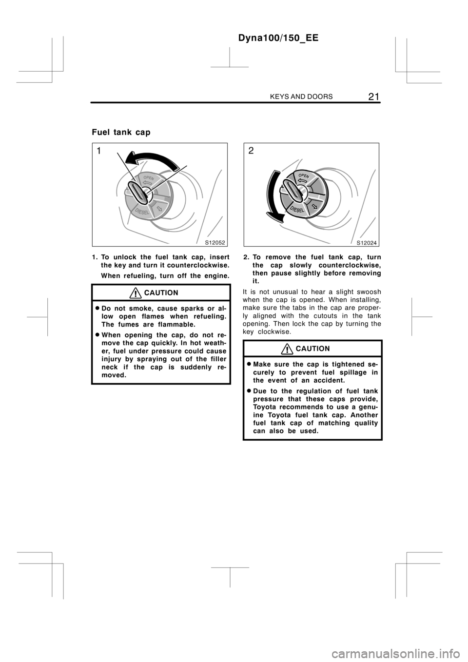
1. To unlock the fuel tank cap, insert
the key and turn it counterclockwise.
When refueling, turn off the engine.
CAUTION
DDo not smoke, cause sparks or al-
low open flames when refueling.
The fumes are flammable.
DWhen opening the cap, do not re-
move the cap quickly. In hot weath-
er, fuel under pressure could cause
injury by spraying out of the filler
neck if the cap is suddenly re-
moved.
2. To remove the fuel tank cap, turn
the cap slowly counterclockwise,
then pause slightly before removing
it.
It is not unusual to hear a slight swoosh
when the cap is opened.When installing,
make sure the tabs in the cap are proper-
ly aligned with the cutouts in the tank
opening. Then lock the cap by turning the
key clockwise.
CAUTION
DMake sure the cap is tightened se-
curely to prevent fuel spillage in
the event of an accident.
DDue to the regulation of fuel tank
pressure that these caps provide,
Toyota recommends to use a genu-
ine Toyota fuel tank cap. Another
fuel tank cap of matching quality
can also be used.
Dyna100/150_EE
Fuel tank cap
Page 73 of 240
GAUGES, METERS AND SERVICE REMINDER INDICATORS67
Section 1−5
OPERATION OF INSTRUMENTS AND
CONTROLS
Gauges, Meters and Service reminder indicators
DFuel gauge 68.........................................
DEngine coolant temperature gauge 68...................
DTachometer 69........................................
DOdometer and two trip meters 70........................
DOil maintenance managementsystem 70................
DService reminder indicators and warning buzzer 73.......
Dyna100/150_EE
Page 74 of 240

68GAUGES, METERS AND SERVICE REMINDER INDICATORS
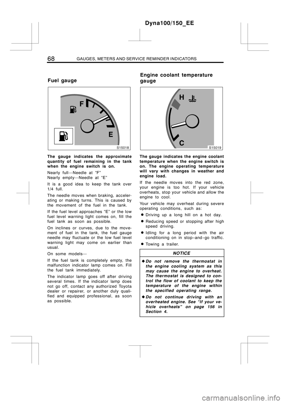
The gauge indicates the approximate
quantity of fuel remaining in the tank
when the engine switch is on.
Nearly full—Needle at “F”
Nearly empty—Needle at “E”
It is a good idea to keep the tank over
1/4 full.
The needle moves when braking, acceler-
ating or making turns. This is caused by
the movement of the fuel in the tank.
If the fuel level approaches “E” or the low
fuel level warning light comes on, fill the
fuel tank as soon as possible.
On inclines or curves, due to the move-
ment of fuel in the tank, the fuel gauge
needle may fluctuate or the low fuel level
warning light may come on earlier than
usual.
On some models—
If the fuel tank is completely empty, the
malfunction indicator lamp comes on. Fill
the fuel tank immediately.
The indicator lamp goes off after driving
several times. If the indicator lamp does
not go off, contact any authorized Toyota
dealer or repairer, or another duly quali-
fied and equipped professional, as soon
as possible.The gauge indicates the engine coolant
temperature when the engine switch is
on. The engine operating temperature
will vary with changes in weather and
engine load.
If the needle moves into the red zone,
your engine is too hot. If your vehicle
overheats, stop your vehicle and allow the
engine to cool.
Your vehicle may overheat during severe
operating conditions, such as:
DDriving up a long hill on a hot day.
DReducing speed or stopping after high
speed driving.
DIdling for a long period with the air
conditioning on in stop−and−go traffic.
DTowingatrailer.
NOTICE
zDo not remove the thermostat in
the engine cooling system as this
may cause the engine to overheat.
The thermostat is designed to con-
trol the flow of coolant to keep the
temperature of the engine within
the specified operating range.
zDo not continue driving with an
overheated engine. See “If your ve-
hicle overheats” on page 156 in
Section 4.
Dyna100/150_EE
Fuel gaugeEngine coolant temperature
gauge