2012 SUBARU TRIBECA transmission
[x] Cancel search: transmissionPage 6 of 420
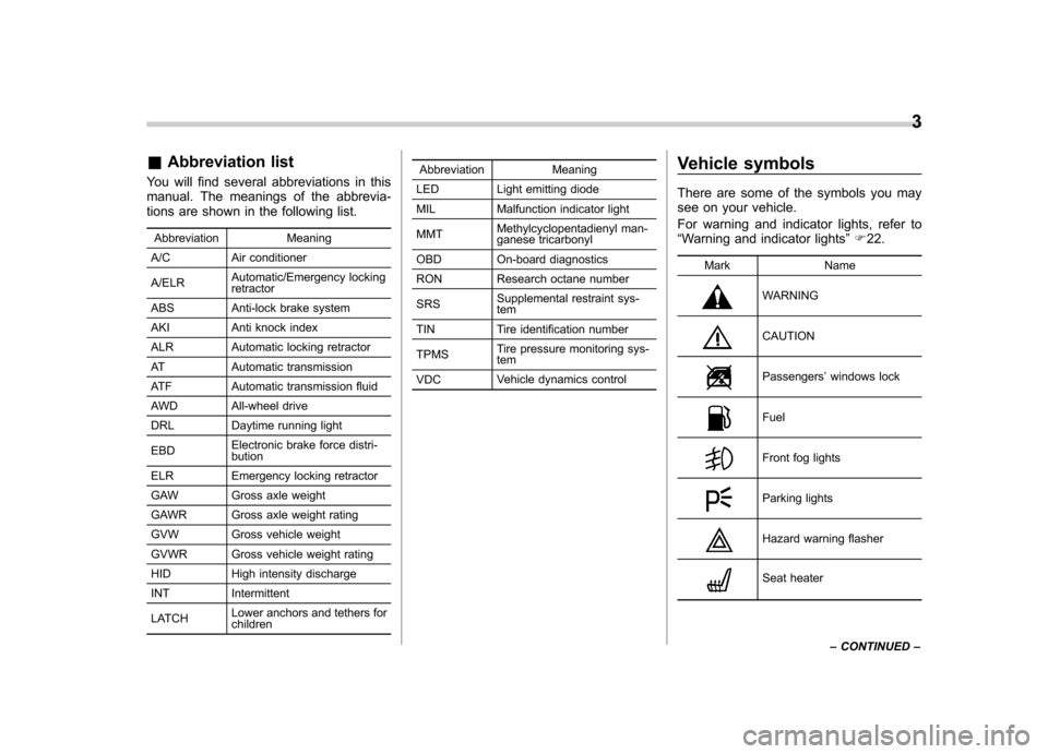
&Abbreviation list
You will find several abbreviations in this
manual. The meanings of the abbrevia-
tions are shown in the following list.
Abbreviation Meaning
A/C Air conditioner A/ELR Automatic/Emergency locking retractor
ABS Anti-lock brake system
AKI Anti knock index
ALR Automatic locking retractor
AT Automatic transmission
ATF Automatic transmission fluid
AWD All-wheel drive
DRL Daytime running light EBD Electronic brake force distri- bution
ELR Emergency locking retractor
GAW Gross axle weight
GAWR Gross axle weight rating
GVW Gross vehicle weight
GVWR Gross vehicle weight rating
HID High intensity discharge
INT Intermittent
LATCH Lower anchors and tethers for children Abbreviation Meaning
LED Light emitting diode
MIL Malfunction indicator light MMT Methylcyclopentadienyl man-
ganese tricarbonyl
OBD On-board diagnostics
RON Research octane number SRS Supplemental restraint sys- tem
TIN Tire identification number TPMS Tire pressure monitoring sys- tem
VDC Vehicle dynamics control Vehicle symbols
There are some of the symbols you may
see on your vehicle.
For warning and indicator lights, refer to “
Warning and indicator lights ”F 22.
Mark Name
WARNING
CAUTION
Passengers ’windows lock
Fuel
Front fog lights
Parking lights
Hazard warning flasher
Seat heater 3
– CONTINUED –
Page 144 of 420
!If the light is blinking
If the light is blinking while driving, an
engine misfire condition has been de-
tected which may damage the emission
control system.
To prevent serious damage to the emis-
sion control system, you should do thefollowing. . Reduce vehicle speed.
. Avoid hard acceleration.
. Avoid steep uphill grades.
. Reduce the amount of cargo, if possi-
ble.. Stop towing a trailer as soon as
possible.
The CHECK ENGINE warning light may
stop blinking and illuminate steadily after
several driving trips. You should have your
vehicle checked by an authorized
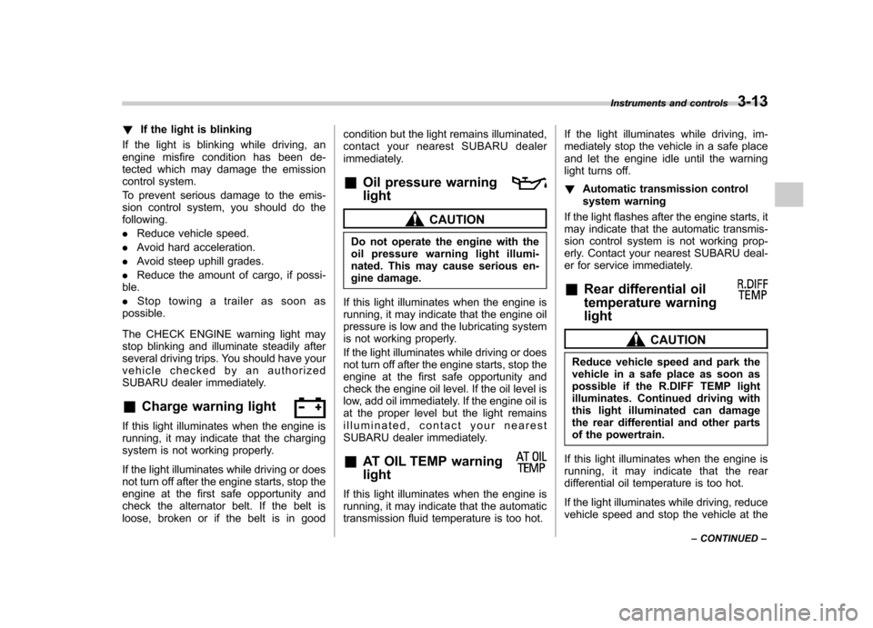
SUBARU dealer immediately. & Charge warning light
If this light illuminates when the engine is
running, it may indicate that the charging
system is not working properly.
If the light illuminates while driving or does
not turn off after the engine starts, stop the
engine at the first safe opportunity and
check the alternator belt. If the belt is
loose, broken or if the belt is in good condition but the light remains illuminated,
contact your nearest SUBARU dealer
immediately.
& Oil pressure warning light
CAUTION
Do not operate the engine with the
oil pressure warning light illumi-
nated. This may cause serious en-
gine damage.
If this light illuminates when the engine is
running, it may indicate that the engine oil
pressure is low and the lubricating system
is not working properly.
If the light illuminates while driving or does
not turn off after the engine starts, stop the
engine at the first safe opportunity and
check the engine oil level. If the oil level is
low, add oil immediately. If the engine oil is
at the proper level but the light remains
illuminated, contact your nearest
SUBARU dealer immediately. & AT OIL TEMP warning light
If this light illuminates when the engine is
running, it may indicate that the automatic
transmission fluid temperature is too hot. If the light illuminates while driving, im-
mediately stop the vehicle in a safe place
and let the engine idle until the warning
light turns off. !
Automatic transmission control
system warning
If the light flashes after the engine starts, it
may indicate that the automatic transmis-
sion control system is not working prop-
erly. Contact your nearest SUBARU deal-
er for service immediately. & Rear differential oil
temperature warning light
CAUTION
Reduce vehicle speed and park the
vehicle in a safe place as soon as
possible if the R.DIFF TEMP light
illuminates. Continued driving with
this light illuminated can damage
the rear differential and other parts
of the powertrain.
If this light illuminates when the engine is
running, it may indicate that the rear
differential oil temperature is too hot.
If the light illuminates while driving, reduce
vehicle speed and stop the vehicle at the Instruments and controls
3-13
– CONTINUED –
Page 167 of 420
3-36Instruments and controls
speed is low; shorter when the vehicle
speed is high).
When you subsequently move the select
lever of the automatic transmission to the“R ” position, the rear wiper will switch to
continuous operation. When you move the
select lever from the “R ”position to some
other position, the rear wiper will return to
intermittent operation. ! Washer
To wash the rear window while the rear
wiper is operating, turn the knob on the
end of the wiper control lever upward tothe “
”position. The washer fluid sprays
until you release the knob.
To wash the rear window when the rear
wiper is not in use, turn the knob on the
end of the wiper control lever downward tothe “
”position. The washer fluid sprays
and the wiper operates until you release
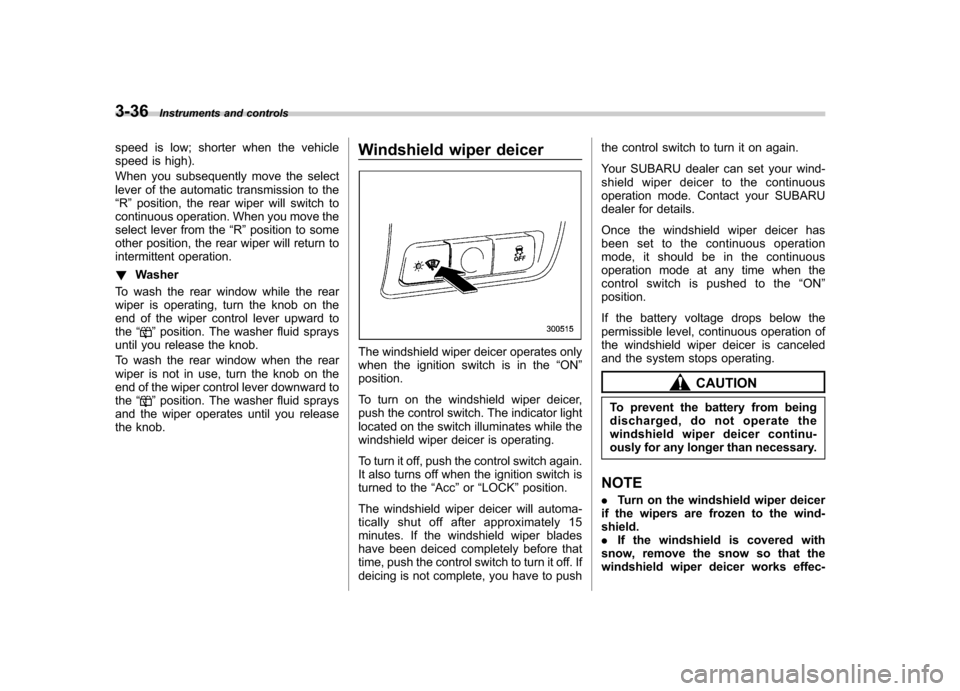
the knob. Windshield wiper deicer
The windshield wiper deicer operates only
when the ignition switch is in the
“ON ”
position.
To turn on the windshield wiper deicer,
push the control switch. The indicator light
located on the switch illuminates while the
windshield wiper deicer is operating.
To turn it off, push the control switch again.
It also turns off when the ignition switch is
turned to the “Acc ”or “LOCK ”position.
The windshield wiper deicer will automa-
tically shut off after approximately 15
minutes. If the windshield wiper blades
have been deiced completely before that
time, push the control switch to turn it off. If
deicing is not complete, you have to push the control switch to turn it on again.
Your SUBARU dealer can set your wind-
shield wiper deicer to the continuous
operation mode. Contact your SUBARU
dealer for details.
Once the windshield wiper deicer has
been set to the continuous operation
mode, it should be in the continuous
operation mode at any time when the
control switch is pushed to the
“ON ”
position.
If the battery voltage drops below the
permissible level, continuous operation of
the windshield wiper deicer is canceled
and the system stops operating.
CAUTION
To prevent the battery from being
discharged, do not operate the
windshield wiper deicer continu-
ously for any longer than necessary.
NOTE . Turn on the windshield wiper deicer
if the wipers are frozen to the wind- shield.. If the windshield is covered with
snow, remove the snow so that the
windshield wiper deicer works effec-
Page 170 of 420
Gear
position Period of
time multi-
function
button is pressed Function
displayed
R (reverse) Briefly
Rear view display ON/OFF*
More than
3 seconds Help lines indica-
tion ON/OFF
Except
R (reverse) Briefly
Auto-dimming
function ON/OFF*
3to6 seconds Electronic com-
pass display ON/ OFF
6to9seconds Enter the com-
pass zone setting mode
9to12 seconds Enter the com-
pass calibration mode
*: The setting returns to “ON ”as a default
setting every time the ignition switch is turned tothe “ON ”position.
! Rear view image display
When the ignition switch is “ON ”and the
select lever is set to “R ”, the rear view
camera automatically displays the rear
view image behind the vehicle on the
inside mirror.
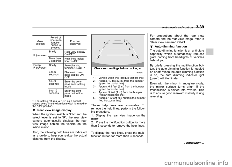
Also, the following help lines are indicated
as a guide to help you realize the actual
distance from the display.
1) Vehicle width line (oblique vertical line)
2) Approx. 10 feet (3 m) from the bumper (green horizontal line)
3) Approx. 6.5 feet (2 m) from the bumper (green horizontal line)
4) Approx. 3 feet (1 m) from the bumper (yellow horizontal line)
5) Approx. 1.5 feet (0.5 m) from the bumper (red horizontal line)
These help lines are removable. To
remove the help lines, perform the follow-
ing procedure.
1. Display the rear view image on the
mirror.
2. Press the multifunction button for more
than 3 seconds to remove the help lines.
To display the help lines, press the multi-
function button for more than 3 seconds. For precautions about the rear view
camera and the rear view image, refer to“
Rear view camera ”F 6-21.
! Auto-dimming function
The auto-dimming function is an anti-glare
capability which automatically reduces
glare coming from headlights of vehicles
behind you.
By briefly pressing the multifunction but-
ton, the auto-dimming function is toggled
on or off. When the auto-dimming function
is on, the auto dimming indicator light
(green) will illuminate.
Even with the mirror in anti-glare mode,
the mirror surface turns bright if the
transmission is shifted into reverse. This
is to ensure good rearward visibility duringreversing. Instruments and controls
3-39
– CONTINUED –
Page 172 of 420
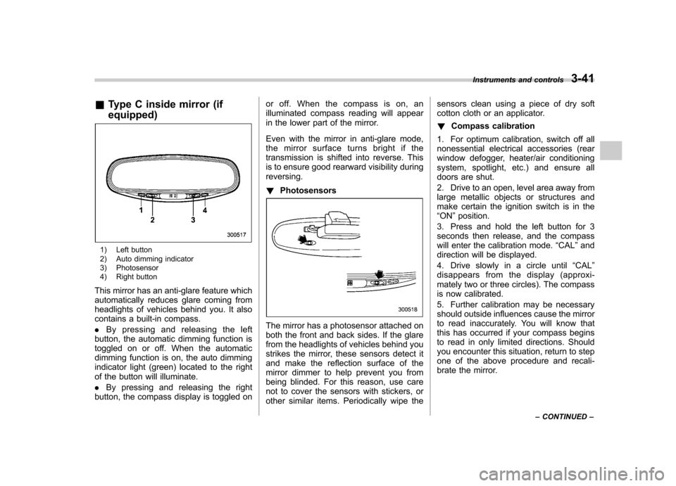
&Type C inside mirror (if equipped)
1) Left button
2) Auto dimming indicator
3) Photosensor
4) Right button
This mirror has an anti-glare feature which
automatically reduces glare coming from
headlights of vehicles behind you. It also
contains a built-in compass. . By pressing and releasing the left
button, the automatic dimming function is
toggled on or off. When the automatic
dimming function is on, the auto dimming
indicator light (green) located to the right
of the button will illuminate. . By pressing and releasing the right
button, the compass display is toggled on or off. When the compass is on, an
illuminated compass reading will appear
in the lower part of the mirror.
Even with the mirror in anti-glare mode,
the mirror surface turns bright if the
transmission is shifted into reverse. This
is to ensure good rearward visibility duringreversing. !
Photosensors
The mirror has a photosensor attached on
both the front and back sides. If the glare
from the headlights of vehicles behind you
strikes the mirror, these sensors detect it
and make the reflection surface of the
mirror dimmer to help prevent you from
being blinded. For this reason, use care
not to cover the sensors with stickers, or
other similar items. Periodically wipe the sensors clean using a piece of dry soft
cotton cloth or an applicator. !
Compass calibration
1. For optimum calibration, switch off all
nonessential electrical accessories (rear
window defogger, heater/air conditioning
system, spotlight, etc.) and ensure all
doors are shut.
2. Drive to an open, level area away from
large metallic objects or structures and
make certain the ignition switch is in the“ ON ”position.
3. Press and hold the left button for 3
seconds then release, and the compass
will enter the calibration mode. “CAL ”and
direction will be displayed.
4. Drive slowly in a circle until “CAL ”
disappears from the display (approxi-
mately two or three circles). The compass
is now calibrated.
5. Further calibration may be necessary
should outside influences cause the mirror
to read inaccurately. You will know that
this has occurred if your compass begins
to read in only limited directions. Should
you encounter this situation, return to step
one of the above procedure and recali-
brate the mirror. Instruments and controls
3-41
– CONTINUED –
Page 246 of 420
Fuel...................................................................... 7-2
Fuel requirements ............................................... 7-2
Fuel filler lid and cap ........................................... 7-3
State emission testing (U.S. only) ...................... 7-5
Preparing to drive ............................................... 7-7
Starting the engine .............................................. 7-7
Stopping the engine ............................................ 7-8
Remote engine start system (dealer option) ..... 7-8
Starting your vehicle ........................................... 7-9
Remote start safety features ................................ 7-9
Entering the vehicle while it is running via remote start .................................................................. 7-9
Entering the vehicle following remote engine start shutdown .......................................................... 7-9
Pre-heating or pre-cooling the interior of the vehicle ............................................................. 7-10
Service mode ..................................................... 7-10
Remote engine start transmitter programming and programmable feature option ..................... 7-10
System maintenance .......................................... 7-11
Automatic transmission ..................................... 7-12
Select lever ........................................................ 7-13
Shift lock function .............................................. 7-14
Selection of manual mode .................................. 7-16
Driving tips ........................................................ 7-17
SPORT mode ..................................................... 7-18 Power steering
................................................... 7-18
Braking ............................................................... 7-19
Braking tips ....................................................... 7-19
Brake system .................................................... 7-19
Disc brake pad wear warning indicators ............. 7-20
ABS (Anti-lock Brake System) .......................... 7-20
ABS system self-check ...................................... 7-21
ABS warning light .............................................. 7-21
Electronic Brake Force Distribution (EBD) system ............................................................. 7-22
Steps to take if EBD system malfunctions ..... ..... 7-22
Vehicle Dynamics Control system .................... 7-23
Vehicle Dynamics Control system monitor..... ..... 7-25
Traction Control system OFF switch ................... 7-25
Tire pressure monitoring system (TPMS) ........ 7-27
Parking your vehicle ......................................... 7-28
Parking brake .................................................... 7-28
Parking tips ....................................................... 7-29
Cruise control .................................................... 7-29
To set cruise control .......................................... 7-30
To temporarily cancel the cruise control ............. 7-30
To turn off the cruise control .............................. 7-31
To change the cruising speed .. .......................... 7-31
Cruise control indicator light .............................. 7-32
Cruise control set indicator light ........................ 7-32
Starting and operating
7
Page 250 of 420
NOTE
.You will see the “”sign in the fuel
gauge. This indicates that the fuel filler
door (lid) is located on the right side of
the vehicle.. If the fuel filler cap is not tightened
until it clicks or if the tether is caught
under the cap, the CHECK ENGINE
warning light/malfunction indicator
light may illuminate. Refer to “CHECK
ENGINE warning light/Malfunction in-
dicator light ”F 3-12.
CAUTION
. Never add any cleaning agents to
the fuel tank. The addition of a
cleaning agent may cause da- mage to the fuel system.
. After refueling, turn the cap to the
right until it clicks to ensure that
it is fully tightened. If the cap is
not securely tightened, fuel may
leak out while the vehicle is being
driven or fuel spillage could
occur in the event of an accident,
creating a fire hazard.
. Do not let fuel spill on the exterior
surfaces of the vehicle. Because
fuel may damage the paint, be
sure to wipe off any spilled fuel
quickly. Paint damage caused by
spilled fuel is not covered under
the SUBARU Limited Warranty.
. Always use a genuine SUBARU
fuel filler cap. If you use the
wrong cap, it may not fit, and
your fuel tank and emission con-
trol system may be damaged. It
could also lead to fuel spillage
and a fire.
. Immediately put fuel in the tank
whenever the low fuel warning
light illuminates. Engine misfires
as a result of an empty tank
could cause damage to the en-gine. State emission testing (U.S. only)
WARNING
Testing of an All-Wheel Drive model
must NEVER be performed on a
single two-wheel dynamometer. At-
tempting to do so will result in
uncontrolled vehicle movement and
may cause an accident or injuries to
persons nearby.
CAUTION
. At state inspection time, remem-
ber to tell your inspection or
service station in advance not to
place your SUBARU AWD vehicle
on a two-wheel dynamometer.
Otherwise, serious transmission
damage will result.
. Resultant vehicle damage due to
improper testing is not covered
under the SUBARU Limited War-
ranty and is the responsibility of
the state inspection program or
its contractors or licensees.
California and a number of federal states
have Inspection/Maintenance programs to Starting and operating
7-5
– CONTINUED –
Page 251 of 420

7-6Starting and operating
inspect your vehicle ’s emission control
system. If your vehicle does not pass this
test, some states may deny renewal of
your vehicle ’s registration.
Your vehicle is equipped with a computer
that monitors the performance of the engine ’s emission control system. Certi-
fied emission inspectors will inspect the
On-Board Diagnostic (OBDII) system as
part of the state emission inspection
process. The OBDII system is designed
to detect engine and transmission pro-
blems that might cause the vehicle emis-
sions to exceed allowable limits. OBDII
inspections apply to all 1996 model year
and newer passenger cars and trucks.
Over 30 states plus the District of Colum-
bia have implemented emission inspec-
tion of the OBDII system. . The inspection of the OBDII system
consists of a visual operational check of the “CHECK ENGINE ”warning light/mal-
function indicator light (MIL) and an
examination of the OBDII system with an
electronic scan tool. . A vehicle
passes the OBDII system
inspection if proper operation of the “ CHECK ENGINE ”warning light is ob-
served, there are no stored diagnostic
trouble codes, and the OBDII readiness
monitors are all complete. .
A vehicle
fails the OBDII inspection if
the “CHECK ENGINE ”warning light is not
properly operating (light is illuminated or is
not working due to a burned out bulb) or
there is one or more diagnostic trouble
codes stored in the vehicle ’s computer.
. A state emission inspection may reject
(not pass or fail) a vehicle if the number of
OBDII system readiness monitors “NOT
READY ”is greater than one. If the
vehicle ’s battery has been recently re-
placed or disconnected, the OBDII system
inspection may indicate that the vehicle is
not ready for the emission test. Under this
condition, the vehicle driver should be
instructed to drive his/her vehicle for a few
days to reset the readiness monitors and
return for an emission re-inspection. . Owners of rejected or failing vehicles
should contact their SUBARU Dealer for service.
Some states still use dynamometers in
their emission inspection program. A
dynamometer is a treadmill or roller-like
testing device that allows your vehicle ’s
wheels to turn while the vehicle remains in
one place. Prior to your vehicle being put
on a dynamometer, tell your emission
inspector
not to place your SUBARU
AWD vehicle on a two-wheel dynam-
ometer. Otherwise, serious transmis-
sion damage will result. The U.S. Environmental Protection
Agency (EPA) and states using two-wheel
dynamometers in their emission testing
program have EXEMPTED SUBARU
AWD vehicles from the portion of the
testing program that involves a two-wheel
dynamometer. There are some states that
use four-wheel dynamometers in their
testing program. When properly used, this
equipment should not damage a SUBARU
AWD vehicle.
Under no circumstances should the rear
wheels be jacked off the ground, nor
should the driveshaft be disconnected for
state emission testing.