2012 SUBARU TRIBECA door lock
[x] Cancel search: door lockPage 137 of 420

3-6Instruments and controls
meter needles and gauges when the
ignition switch is turned to the “ON ”
position. To change the current setting,
press the trip knob for at least 2 seconds.
: Activated
: Deactivated
With the function deactivated, the combi-
nation meter illuminates as follows.
1. Warning lights, indicator lights, meter
rims, meter needles, odometer, trip meter,
and gauge back lights illuminate.
2. Meter and gauge dials illuminate.
3. Regular illumination (for driving) be- gins.
Briefly press the trip knob again. You can
now establish the activated/deactivated
setting for sequential illumination of the combination meter when the ignition
switch is turned to the
“ON ”position. To
change the current setting, press the trip
knob for at least 2 seconds.
: Activated
: Deactivated
Briefly press the knob to return to the A trip
meter indication.
If you turn the ignition switch to the “ LOCK ”position, turn the ignition switch
to the “ON ”position, or open and close the
driver ’s door during the setting procedure,
the new setting will be canceled.
Also, if you do not press the trip knob for a
period of 10 seconds, the new setting will
be canceled. NOTE . It is not possible to cancel sequen-
tial illumination of the combination
meter while sequential illumination is
actually taking place. Cancel sequen-
tial illumination when regular illumina-
tion (for driving) has begun.. When you open the driver ’s door
with the ignition switch in the “LOCK ”
position, the meters ’needles and rims
are lit. The illumination stops working
when you shut the driver ’s door or
automatically after 30 seconds. &
Speedometer
The speedometer shows the vehiclespeed. & Odometer
This meter displays the odometer when
the ignition switch is in the “LOCK ”, “Acc ”
or “ON ”position.
The odometer shows the total distance
that the vehicle has been driven.
If you press the trip knob when the ignition
switch is in the “LOCK ”or “Acc ”position,
the odometer/trip meter will light up. If you
do not press the trip knob within 10
seconds of illumination of the odometer/
trip meter, the odometer/trip meter will turnoff.
Page 138 of 420

The odometer/trip meter will also turn off if
you open and close the driver’sdoor
within 10 seconds of illumination of the
odometer/trip meter. & Double trip meter
This meter displays two trip meters when
the ignition switch is in the “LOCK ”, “Acc ”
or “ON ”position.
The trip meter shows the distance that the
vehicle has been driven since you last set
it to zero.
To change the mode indication, briefly
push the knob.
Each press of the knob changes the mode
indication alternately.
To set the trip meter to zero, select the A
trip or B trip meter by pushing the knob
and keep the knob pushed for more than 2seconds.
If you press the trip knob when the ignition
switch is in the “LOCK ”position, the
odometer/trip meter will light up. It is
possible to switch between the A trip
meter and B trip meter indications while
the odometer/trip meter is lit up. If you do
not press the trip knob within 10 seconds
of illumination of the odometer/trip meter,
the odometer/trip meter will turn off. Also,
if you open and close the driver ’s door
within 10 seconds of illumination of the
odometer/trip meter, the odometer/trip
meter will turn off.
CAUTION
To ensure safety, do not attempt to
change the function of the indicator
during driving, as an accident couldresult. NOTE
If the connection between the combina-
tion meter and battery is broken for any
reason such as vehicle maintenance or
fuse replacement, the data recorded on
the trip meter will be lost. !
Vehicle communication system
malfunction indication
The vehicle communication system car-
ries various types of information (vehicle
speed, running conditions, etc.) to control
modules. In the event of a malfunction in
this communication system, the trip meter
will show “
”.
If the trip meter shows “
”, immediately
contact the nearest SUBARU dealer and
have the vehicle communication systeminspected. NOTE
If you press the trip knob while the trip
meter is showing “
”, the trip meter
indication will appear for 10 seconds.
& Tachometer
The tachometer shows the engine speed
in thousands of revolutions per minute.
CAUTION
Do not operate the engine with the Instruments and controls
3-7
– CONTINUED –
Page 139 of 420

3-8Instruments and controls
pointer of the tachometer in the red
zone. This may cause severe da-
mage to the engine.
NOTE
To protect the engine while the select
lever is in the “P ” or “N ” position, the
engine is controlled so that the engine
speed may not become too high even if
the accelerator pedal is depressedhard. & Fuel gauge
The fuel gauge shows the approximate
amount of fuel remaining in the tank.
The gauge may move slightly during
braking, turning or acceleration due to fuel level movement in the tank.
If you press the trip knob while the ignition
switch is in the
“LOCK ”or “Acc ”position,
the fuel gauge will light up and indicate the
amount of fuel remaining in the tank. NOTE
You will see the “”sign in the fuel
gauge meter.
This indicates that the fuel filler door
(lid) is located on the right side of thevehicle. &
Temperature gauge
1) Normal operating range
The temperature gauge shows engine
coolant temperature when the ignition
switch is in the “ON ”position.
The coolant temperature will vary in
accordance with the outside temperature
and driving conditions.
We recommend that you drive moderately
until the pointer of the temperature gauge
reaches near the middle of the range.
Engine operation is optimum with the
engine coolant at this temperature range.
Also, high revving operation while the
engine is not sufficiently warmed up
should be avoided.
Page 221 of 420

6-2Interior equipment
Interior light
When leaving your vehicle, make sure the
lights are turned off to avoid batterydischarge. &Dome light
Models with Rear Seat Entertainment
Models without Rear Seat Entertainment
1) ON
2) DOOR
3) OFF
The dome light switch has the following
three positions. ON: The light remains on continuously.
OFF: The light remains off.
DOOR: The dome light illuminates auto-
matically in the following cases. . Any of the doors or the rear gate is
opened.. The doors or the rear gate are un-
locked using the remote keyless entry
transmitter. . The ignition switch is turned from the
“ Acc ”position to the “LOCK ”position. The automatically illuminated dome light
remains on for several seconds and then
gradually turns off after all doors and the
rear gate are closed. While the light is
illuminated, if any of the following opera-
tions are performed, the dome light turns
off immediately. .
The ignition switch is turned from the
“ LOCK ”position to “Acc ”or “ON ”position.
. All doors and the rear gate are locked
using the remote keyless entry transmitter.
The setting of the period for which the light
remains on (OFF delay timer) can be
changed by a SUBARU dealer. Contact
the nearest SUBARU dealer for details.
Page 223 of 420

6-4Interior equipment
(automatic illumination - ON).
. The doors are unlocked using the
remote keyless entry transmitter. . The ignition switch is turned from the
“ Acc ”position to the “LOCK ”position.
The automatically illuminated map lights
remain illuminated for several seconds
and then gradually turn off after all doors
are closed.
While the lights are illuminated, if any of
the following operations are performed,
the map lights turn off immediately. . The ignition switch is turned from the
“ LOCK ”position to the “Acc ”or “ON ”
position.. All doors and the rear gate are locked
using the remote keyless entry transmitter.
The setting of the period for which the light
remains illuminated (OFF delay timer) can
be changed by a SUBARU dealer. Con-
tact your SUBARU dealer for details.
NOTE
If any of the doors or the rear gate is
not completely closed, the map lights
will remain illuminated as a result.
However, the map lights are automati-
cally turned off by the battery drainage
prevention functi on to prevent the
battery from discharging. For details, refer to
“Battery drainage prevention
function ”F 2-6.
& Automatic ambient light for
center console area (if equipped)
The automatic ambient light illuminates
when the ignition switch is in the “ON ”
position and the light control switch is inthe “
”position or “”position. The
light dimly illuminates the area around the
center console. The light turns off when
the light control switch is in the “OFF ”
position. Also, the brightness of the light is
adjusted by the illumination brightness
control dial. Sun visors
To block out glare, swing down the visors.
To use the sun visor at a side window,
swing it down and move it sideways.
Page 236 of 420

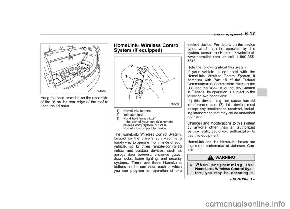
Hang the hook provided on the underside
of the lid on the rear edge of the roof to
keep the lid open.HomeLink
®Wireless Control
System (if equipped)
1) HomeLink®buttons
2) Indicator light
3) Hand-held transmitter* * Not part of your vehicle ’s remote
keyless entry system but of a HomeLink
®-compatible device.
The HomeLink
®Wireless Control System,
located on the driver ’s sun visor, is a
handy way to operate, from inside of your
vehicle, up to three remote-controlled
indoor and outdoor devices, such as
garage door openers, entrance gates,
door locks, home lighting, and security
systems. There are three HomeLink
®buttons on the sun visor, each of which
you can program for operation of one desired device. For details on the device
types which can be operated by this
system, consult the HomeLink website at
www.homelink.com or call 1-800-355-3515.
Note the following about this system:
If your vehicle is equipped with the HomeLink
®Wireless Control System, it
complies with Part 15 of the Federal
Communication Commission Rules in the
U.S. and the RSS-210 of Industry Canada
in Canada. Its operation is subject to the
following two conditions:
(1) this device may not cause harmful
interference, and (2) this device must
accept any interference received, includ-
ing interference that may cause undesiredoperation.
Changes and modifications to this system
by anyone other than an authorized
service facility could void authorization to
use this equipment.
HomeLink and the HomeLink house are
registered trademarks of Johnson Con-
trols, Inc.
WARNING
. When programming the
HomeLink
®Wireless Control Sys-
tem, you may be operating a Interior equipment
6-17
– CONTINUED –
Page 240 of 420

opener by pressing the programmed HomeLink®button.
& Programming other devices
To program other devices such as door
locks, home lighting and security systems,
contact HomeLink at www.homelink.com
or call 1-800-355-3515. & Operating the HomeLink
®
Wireless Control System
Once programmed, the HomeLink
®Wire-
less Control System can be used to
remote-control the devices to which its
buttons are programmed. To activate a
device, simply press the appropriate but-
ton. The indicator light illuminates, indicat-
ing that the signal is being transmitted.
& Erasing HomeLink
®button
memory
NOTE . Performing this procedure erases
the memory of all the preprogrammed
buttons simultaneously. The memory
of individual buttons cannot be erased. . It is recommended that upon the
sale of the vehicle, the memory of all
programmed HomeLink
®buttons be
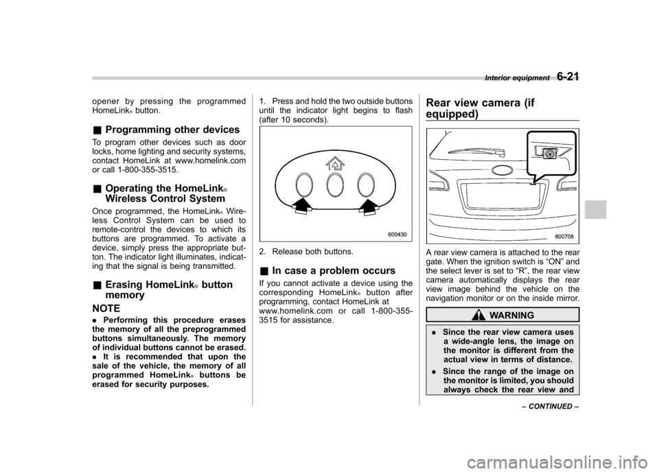
erased for security purposes. 1. Press and hold the two outside buttons
until the indicator light begins to flash
(after 10 seconds).
2. Release both buttons. &
In case a problem occurs
If you cannot activate a device using the
corresponding HomeLink
®button after
programming, contact HomeLink at
www.homelink.com or call 1-800-355-
3515 for assistance. Rear view camera (if
equipped)
A rear view camera is attached to the rear
gate. When the ignition switch is
“ON ”and
the select lever is set to “R ”, the rear view
camera automatically displays the rear
view image behind the vehicle on the
navigation monitor or on the inside mirror.
WARNING
. Since the rear view camera uses
a wide-angle lens, the image on
the monitor is different from the
actual view in terms of distance.
. Since the range of the image on
the monitor is limited, you should
always check the rear view and Interior equipment
6-21
– CONTINUED –
Page 249 of 420

7-4Starting and operating
WARNING
Before opening the fuel filler cap,
first touch the vehicle body or a
metal portion of the fuel pump or
similar object to discharge any
static electricity that may be present
on your body. If your body is carry-
ing an electrostatic charge, there is
a possibility that an electric spark
could ignite the fuel, which could
burn you. To avoid acquiring a new
static electric charge, do not get
back into the vehicle while refueling
is in progress.
1) Open
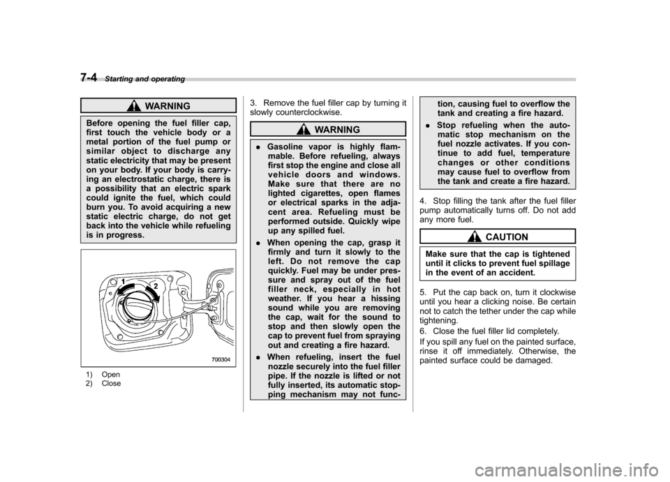
2) Close 3. Remove the fuel filler cap by turning it
slowly counterclockwise.
WARNING
. Gasoline vapor is highly flam-
mable. Before refueling, always
first stop the engine and close all
vehicle doors and windows.
Make sure that there are no
lighted cigarettes, open flames
or electrical sparks in the adja-
cent area. Refueling must be
performed outside. Quickly wipe
up any spilled fuel.
. When opening the cap, grasp it
firmly and turn it slowly to the
left. Do not remove the cap
quickly. Fuel may be under pres-
sure and spray out of the fuel
filler neck, especially in hot
weather. If you hear a hissing
sound while you are removing
the cap, wait for the sound to
stop and then slowly open the
cap to prevent fuel from spraying
out and creating a fire hazard.
. When refueling, insert the fuel
nozzle securely into the fuel filler
pipe. If the nozzle is lifted or not
fully inserted, its automatic stop-
ping mechanism may not func- tion, causing fuel to overflow the
tank and creating a fire hazard.
. Stop refueling when the auto-
matic stop mechanism on the
fuel nozzle activates. If you con-
tinue to add fuel, temperature
changes or other conditions
may cause fuel to overflow from
the tank and create a fire hazard.
4. Stop filling the tank after the fuel filler
pump automatically turns off. Do not add
any more fuel.
CAUTION
Make sure that the cap is tightened
until it clicks to prevent fuel spillage
in the event of an accident.
5. Put the cap back on, turn it clockwise
until you hear a clicking noise. Be certain
not to catch the tether under the cap whiletightening.
6. Close the fuel filler lid completely.
If you spill any fuel on the painted surface,
rinse it off immediately. Otherwise, the
painted surface could be damaged.