2012 SUBARU TRIBECA wheel
[x] Cancel search: wheelPage 175 of 420
3-44Instruments and controls
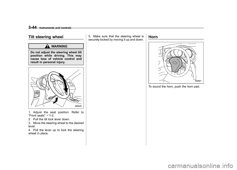
Tilt steering wheel
WARNING
Do not adjust the steering wheel tilt
position while driving. This may
cause loss of vehicle control and
result in personal injury.
1. Adjust the seat position. Refer to “ Front seats ”F 1-2.
2. Pull the tilt lock lever down.
3. Move the steering wheel to the desired level.
4. Pull the lever up to lock the steering
wheel in place. 5. Make sure that the steering wheel is
securely locked by moving it up and down.
Horn
To sound the horn, push the horn pad.
Page 179 of 420
4-4Climate control
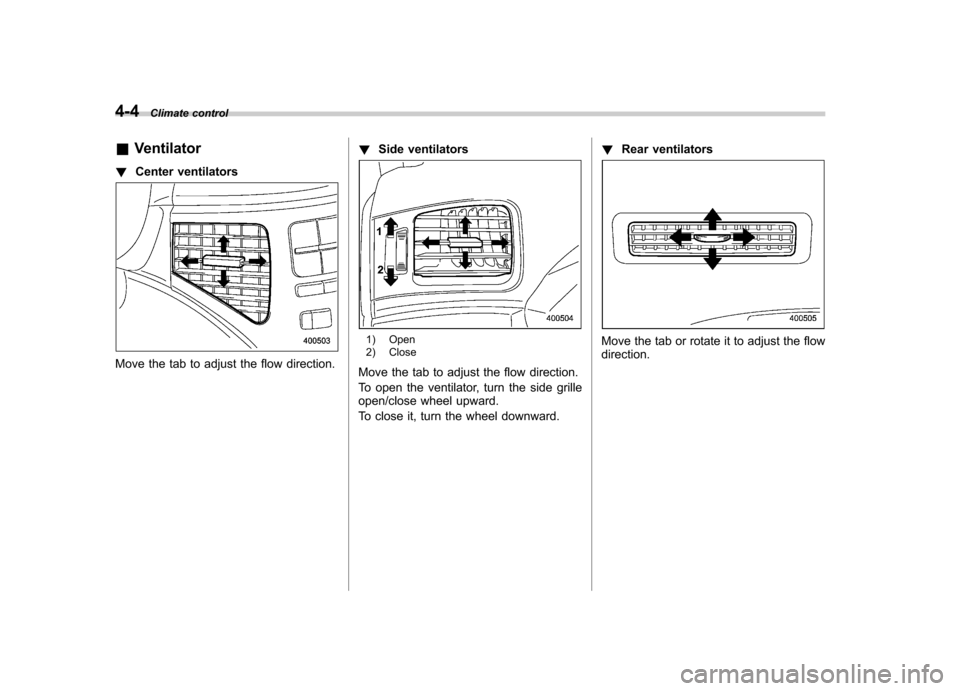
& Ventilator
! Center ventilators
Move the tab to adjust the flow direction. !
Side ventilators
1) Open
2) Close
Move the tab to adjust the flow direction.
To open the ventilator, turn the side grille
open/close wheel upward.
To close it, turn the wheel downward. !
Rear ventilatorsMove the tab or rotate it to adjust the flow direction.
Page 215 of 420
5-26Audio
!How to unload CDs from the player
! Ejecting a CD from the player
Of the discs loaded, you can select and
remove only one disc.
1. Use the disc select button (9) to select
the disc to be ejected.
2. Briefly press the “
”button (8). The
selected disc will be ejected. The disc
number indicator will flash at this time.
When you remove the ejected disc, the
disc number indicator will turn off.
To remove more discs in succession,
repeat Steps 1 and 2. ! Ejecting all discs from the player (all
disc ejection mode)
1. If you press and hold the “
”button
(8), the player will produce a beep sound
and will enter the all disc ejection mode.
2. Remove the disc that has been
ejected. The other discs loaded will then
be ejected one after another. If you do not
remove the disc that has been ejected, the“ All disc ejection mode ”will be canceled.
NOTE . Avoid driving the vehicle with a CD
sticking out, because vibration might
make it fall out.. If you press the “
”button while the player is in all disc ejection mode,
the mode will be cancelled following
ejection of the disc that is currently
being ejected..
If you press the “CD ”button while
the player is in all disc ejection mode,
the player will draw in the discs that
have been ejected and play them. Audio control buttons
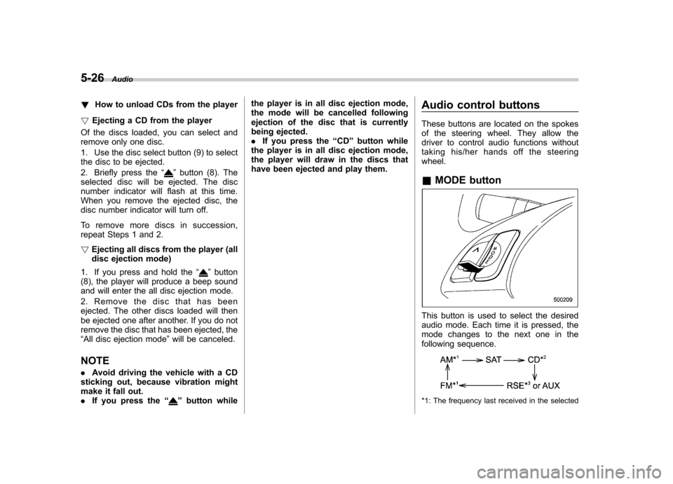
These buttons are located on the spokes
of the steering wheel. They allow the
driver to control audio functions without
taking his/her hands off the steeringwheel. &
MODE button
This button is used to select the desired
audio mode. Each time it is pressed, the
mode changes to the next one in the
following sequence.
*1: The frequency last received in the selected
Page 250 of 420
NOTE
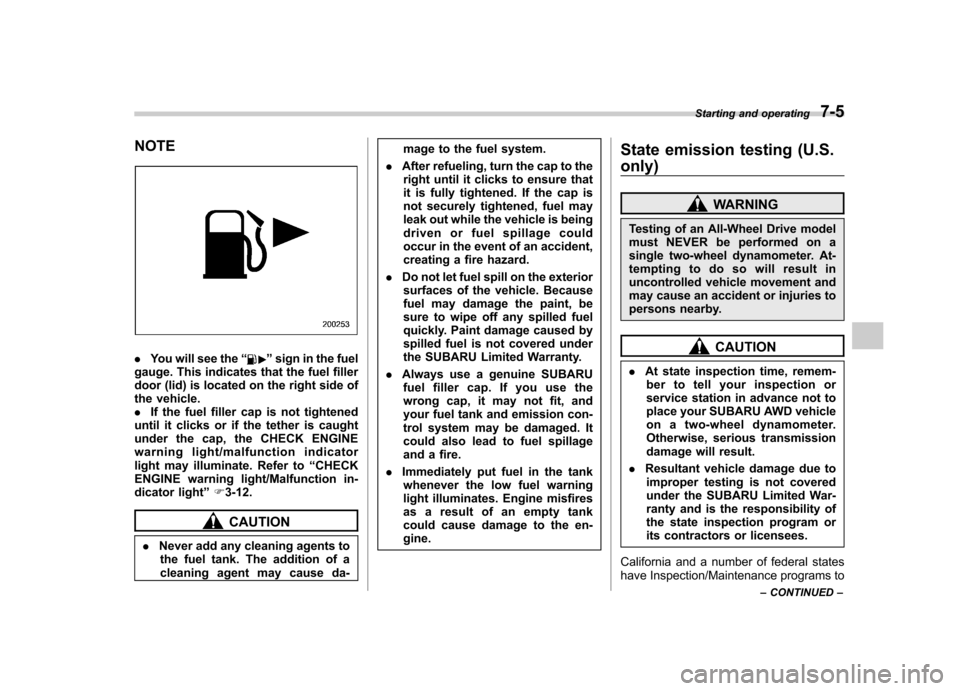
.You will see the “”sign in the fuel
gauge. This indicates that the fuel filler
door (lid) is located on the right side of
the vehicle.. If the fuel filler cap is not tightened
until it clicks or if the tether is caught
under the cap, the CHECK ENGINE
warning light/malfunction indicator
light may illuminate. Refer to “CHECK
ENGINE warning light/Malfunction in-
dicator light ”F 3-12.
CAUTION
. Never add any cleaning agents to
the fuel tank. The addition of a
cleaning agent may cause da- mage to the fuel system.
. After refueling, turn the cap to the
right until it clicks to ensure that
it is fully tightened. If the cap is
not securely tightened, fuel may
leak out while the vehicle is being
driven or fuel spillage could
occur in the event of an accident,
creating a fire hazard.
. Do not let fuel spill on the exterior
surfaces of the vehicle. Because
fuel may damage the paint, be
sure to wipe off any spilled fuel
quickly. Paint damage caused by
spilled fuel is not covered under
the SUBARU Limited Warranty.
. Always use a genuine SUBARU
fuel filler cap. If you use the
wrong cap, it may not fit, and
your fuel tank and emission con-
trol system may be damaged. It
could also lead to fuel spillage
and a fire.
. Immediately put fuel in the tank
whenever the low fuel warning
light illuminates. Engine misfires
as a result of an empty tank
could cause damage to the en-gine. State emission testing (U.S. only)
WARNING
Testing of an All-Wheel Drive model
must NEVER be performed on a
single two-wheel dynamometer. At-
tempting to do so will result in
uncontrolled vehicle movement and
may cause an accident or injuries to
persons nearby.
CAUTION
. At state inspection time, remem-
ber to tell your inspection or
service station in advance not to
place your SUBARU AWD vehicle
on a two-wheel dynamometer.
Otherwise, serious transmission
damage will result.
. Resultant vehicle damage due to
improper testing is not covered
under the SUBARU Limited War-
ranty and is the responsibility of
the state inspection program or
its contractors or licensees.
California and a number of federal states
have Inspection/Maintenance programs to Starting and operating
7-5
– CONTINUED –
Page 251 of 420

7-6Starting and operating
inspect your vehicle ’s emission control
system. If your vehicle does not pass this
test, some states may deny renewal of
your vehicle ’s registration.
Your vehicle is equipped with a computer
that monitors the performance of the engine ’s emission control system. Certi-
fied emission inspectors will inspect the
On-Board Diagnostic (OBDII) system as
part of the state emission inspection
process. The OBDII system is designed
to detect engine and transmission pro-
blems that might cause the vehicle emis-
sions to exceed allowable limits. OBDII
inspections apply to all 1996 model year
and newer passenger cars and trucks.
Over 30 states plus the District of Colum-
bia have implemented emission inspec-
tion of the OBDII system. . The inspection of the OBDII system
consists of a visual operational check of the “CHECK ENGINE ”warning light/mal-
function indicator light (MIL) and an
examination of the OBDII system with an
electronic scan tool. . A vehicle
passes the OBDII system
inspection if proper operation of the “ CHECK ENGINE ”warning light is ob-
served, there are no stored diagnostic
trouble codes, and the OBDII readiness
monitors are all complete. .
A vehicle
fails the OBDII inspection if
the “CHECK ENGINE ”warning light is not
properly operating (light is illuminated or is
not working due to a burned out bulb) or
there is one or more diagnostic trouble
codes stored in the vehicle ’s computer.
. A state emission inspection may reject
(not pass or fail) a vehicle if the number of
OBDII system readiness monitors “NOT
READY ”is greater than one. If the
vehicle ’s battery has been recently re-
placed or disconnected, the OBDII system
inspection may indicate that the vehicle is
not ready for the emission test. Under this
condition, the vehicle driver should be
instructed to drive his/her vehicle for a few
days to reset the readiness monitors and
return for an emission re-inspection. . Owners of rejected or failing vehicles
should contact their SUBARU Dealer for service.
Some states still use dynamometers in
their emission inspection program. A
dynamometer is a treadmill or roller-like
testing device that allows your vehicle ’s
wheels to turn while the vehicle remains in
one place. Prior to your vehicle being put
on a dynamometer, tell your emission
inspector
not to place your SUBARU
AWD vehicle on a two-wheel dynam-
ometer. Otherwise, serious transmis-
sion damage will result. The U.S. Environmental Protection
Agency (EPA) and states using two-wheel
dynamometers in their emission testing
program have EXEMPTED SUBARU
AWD vehicles from the portion of the
testing program that involves a two-wheel
dynamometer. There are some states that
use four-wheel dynamometers in their
testing program. When properly used, this
equipment should not damage a SUBARU
AWD vehicle.
Under no circumstances should the rear
wheels be jacked off the ground, nor
should the driveshaft be disconnected for
state emission testing.
Page 253 of 420
7-8Starting and operating
started. The fuel injection system auto-
matically lowers the idle speed as the
engine warms up.
While the engine is warming up, make
sure that the select lever is at the “P ” or
“ N ”position and that the parking brake is
applied. NOTE . The engine may be difficult to start
when the battery has been discon-
nected and reconnected (for mainte-
nance or other purposes). This diffi-
culty is caused by the electronically
controlled throttle ’s self-diagnosis
function. To overcome it, keep the
ignition switch in the “ON ”position
for approximately 10 seconds before
starting the engine.. To protect the engine while the
select lever is in the “P ” or “N ”
position, the engine is controlled so
that the engine speed may not become
too high even if the accelerator pedal is
depressed hard. Stopping the engine
WARNING
Do not stop the engine when the
vehicle is moving. This will cause
loss of power to the power steering
and the brake booster, making steer-
ing and braking more difficult. It
could also result in accidental acti-
vation of the “LOCK ”position on the
ignition switch, causing the steering
wheel to lock.
The ignition switch should be turned off
only when the vehicle is stopped and the
engine is idling. Remote engine start system
(dealer option)
WARNING
. Do not start the engine using the
remote start system in an en-
closed environment (e.g. closed
garage). Prolonged operation of
a motor vehicle in an enclosed
environment can cause a harmful
build-up of Carbon Monoxide.
Carbon Monoxide is harmful to
your health. Exposure to high
levels of Carbon Monoxide can
cause headaches, dizziness or in
extreme cases unconsciousness
and/or death.
. Before performing any servicing
of the vehicle, temporarily place
the remote engine start system in
service mode to prevent the
system from unexpectedly start-
ing the engine.
Page 257 of 420
7-12Starting and operating
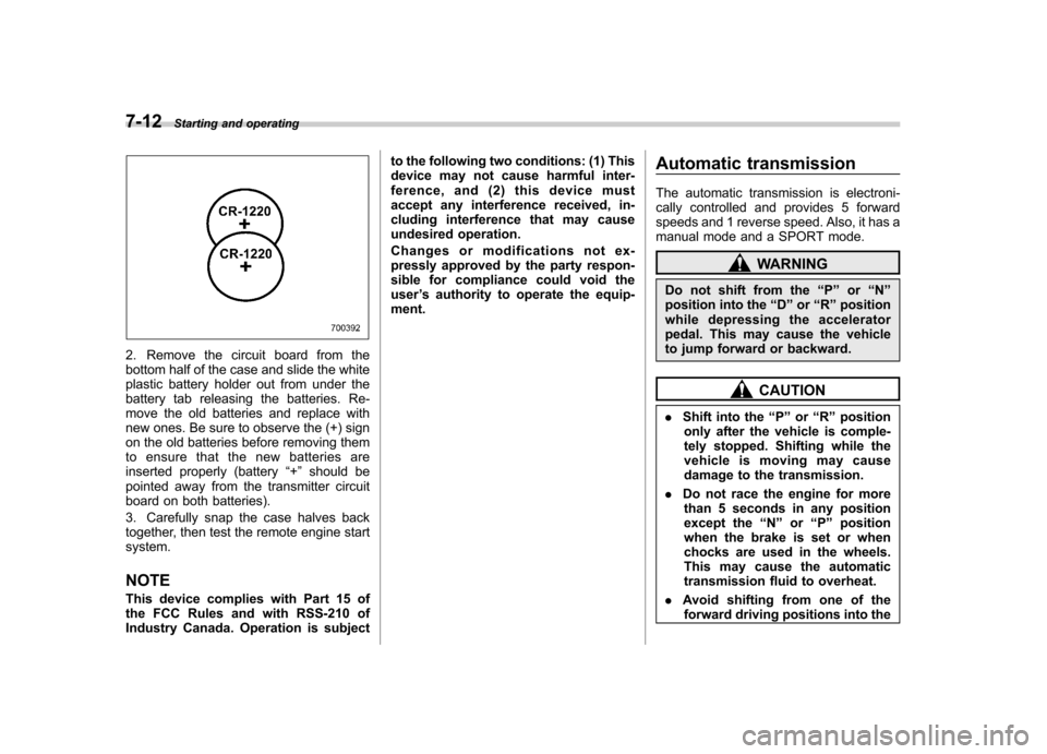
2. Remove the circuit board from the
bottom half of the case and slide the white
plastic battery holder out from under the
battery tab releasing the batteries. Re-
move the old batteries and replace with
new ones. Be sure to observe the (+) sign
on the old batteries before removing them
to ensure that the new batteries are
inserted properly (battery “+ ” should be
pointed away from the transmitter circuit
board on both batteries).
3. Carefully snap the case halves back
together, then test the remote engine startsystem.
NOTE
This device complies with Part 15 of
the FCC Rules and with RSS-210 of
Industry Canada. Operation is subject to the following two conditions: (1) This
device may not cause harmful inter-
ference, and (2) this device must
accept any interference received, in-
cluding interference that may cause
undesired operation.
Changes or modifications not ex-
pressly approved by the party respon-
sible for compliance could void theuser
’s authority to operate the equip-
ment. Automatic transmission
The automatic transmission is electroni-
cally controlled and provides 5 forward
speeds and 1 reverse speed. Also, it has a
manual mode and a SPORT mode.
WARNING
Do not shift from the “P ” or “N ”
position into the “D ” or “R ” position
while depressing the accelerator
pedal. This may cause the vehicle
to jump forward or backward.
CAUTION
. Shift into the “P ” or “R ” position
only after the vehicle is comple-
tely stopped. Shifting while the
vehicle is moving may cause
damage to the transmission.
. Do not race the engine for more
than 5 seconds in any position
except the “N ” or “P ” position
when the brake is set or when
chocks are used in the wheels.
This may cause the automatic
transmission fluid to overheat.
. Avoid shifting from one of the
forward driving positions into the
Page 259 of 420
7-14Starting and operating
is started.
If the select lever does not move from the “P ” position with the brake pedal de-
pressed, the select lever button pushed
in, and the ignition switch in the ON
position, refer to “Shift lock function ”F 7-
14. ! R (Reverse)
This position is for backing the vehicle.
To shift from the “N ” to “R ”position, stop
the vehicle completely then move the
lever to the “R ” position while pushing
the select lever button. ! N (Neutral)
This position is for restarting a stalled engine.
In this position the wheels and transmis-
sion are not locked. In this position, the
transmission is neutral; the vehicle will roll
freely, even on the slightest incline unless
the parking brake or foot brake is applied.
Avoid coasting with the transmission neutral.
During coasting, there is no engine brak-
ing effect.
NOTE
When the ignition switch has been
turned to the “LOCK ”position, move-
ment of the select lever from the “N ” position to the
“R ” position is possible
for a limited time period by depressing
the brake pedal and then becomes
impossible. If the select lever becomes
impossible to be moved after a limited
time period, turn the ignition switch tothe “ON ”position. You will then be able
to move the select lever to the “P ”
position.
WARNING
Do not drive the vehicle with the
select lever in the “N ” (Neutral)
position. Engine braking has no
effect in this condition and the risk
of an accident is consequently in-creased.
! D (Drive)
This position is for normal driving.
The transmission automatically shifts into
a suitable gear from 1st to 5th according to
the vehicle speed and the acceleration
you require.
When more acceleration is required in this
position, depress the accelerator pedal
fully to the floor and hold that position. The
transmission will automatically downshift
to 4th, 3rd, 2nd or 1st gear. When you
release the pedal, the transmission will return to the original gear position.
To use the SPORT mode, move the lever
from this position into the manual gate.
To use the manual mode, move the lever
from this position into the manual gate
then move it toward the
“+ ” and “� ” ends.
! While climbing a grade
When driving up a hill, undesired upshift to
4th or 5th gear is prevented from taking
place when the accelerator is released.
This minimizes the chance of subsequent
downshifting to a lower gear when accel-
erating again. This prevents repeated
upshifting and downshifting resulting in a
smoother operation of the vehicle.
NOTE
The transmission may downshift to 2nd
or 1st gear, depending on the way the
accelerator pedal is depressed to ac-
celerate the vehicle again. & Shift lock function
The shift lock function helps prevent the
improper operation of the select lever. . The select lever cannot be operated
unless the ignition switch is turned to the “ ON ”position and the brake pedal is
depressed. . The select lever cannot be moved from