2012 SUBARU TRIBECA warning light
[x] Cancel search: warning lightPage 75 of 420

1-46Seat, seatbelt and SRS airbags
refer to “Seatbelts ”F 1-17.
. Do not sit or lean unnecessarily
close to the SRS airbag. Because
the SRS airbag deploys with
considerable speed –faster than
the blink of an eye –and force to
protect in high speed collisions,
the force of an airbag can injure
an occupant whose body is too
close to SRS airbag.
It is also important to wear your
seatbelt to help avoid injuries
that can result when the SRS
airbag contacts an occupant not
in proper position such as one
thrown forward during pre-acci-
dent braking.
Even when properly positioned,
there remains a possibility that
an occupant may suffer minor
injury such as abrasions and
bruises to the face or arms
because of the SRS airbag de-
ployment force.
. The SRS airbags deploy with
considerable speed and force.
Occupants who are out of proper
position when the SRS airbag
deploys could suffer very serious
injuries. Because the SRS airbag
needs enough space for deploy- ment, the driver should always
sit upright and well back in the
seat as far from the steering
wheel as practical while still
maintaining full vehicle control
and the front passenger should
move the seat as far back as
possible and sit upright and well
back in the seat.
. Do not place any objects over or
near the SRS airbag cover or
between you and the SRS airbag.
If the SRS airbag deploys, those
objects could interfere with its
proper operation and could be
propelled inside the vehicle and
cause injury.WARNING
. Put children aged 12 and under in
a rear seat properly restrained at
all times. The SRS airbag de-
ploys with considerable speed
and force and can injure or even
kill children, especially if they are
12 years of age and under and
are not restrained or improperly
restrained. Because children are
lighter and weaker than adults,
their risk of being injured from
deployment is greater.
Consequently, we strongly re-
commend that ALL children (in-
cluding those in child seats and
those that have outgrown child
restraint devices) sit in a REAR
seat properly restrained at all
times in a child restraint device
or in a seatbelt, whichever is
appropriate for the child ’s age,
height and weight.
Always secure ALL types of child
restraint devices (including for-
ward facing child seats) in one of
the rear seating positions recom-
mended in this Owner ’s Manual.
According to accident statistics,
children are safer when properly
Page 77 of 420
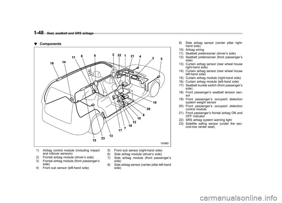
1-48Seat, seatbelt and SRS airbags
! Components
1) Airbag control module (including impact
and rollover sensors)
2) Frontal airbag module (driver ’s side)
3) Frontal airbag module (front passenger ’s
side)
4) Front sub sensor (left-hand side) 5) Front sub sensor (right-hand side)
6) Side airbag module (driver
’s side)
7) Side airbag module (front passenger ’s
side)
8) Side airbag sensor (center pillar left-hand side) 9) Side airbag sensor (center pillar right-
hand side)
10) Airbag wiring
11) Seatbelt pretensioner (driver ’s side)
12) Seatbelt pretensioner (front passenger ’s
side)
13) Curtain airbag sensor (rear wheel house right-hand side)
14) Curtain airbag sensor (rear wheel house left-hand side)
15) Curtain airbag module (right-hand side)
16) Curtain airbag module (left-hand side)
17) Seatbelt buckle switch (front passenger ’s
side)
18) Front passenger ’s seatbelt tension sen-
sor
19) Front passenger ’s occupant detection
system weight sensor
20) Front passenger ’s occupant detection
control module
21) Front passenger ’s frontal airbag ON and
OFF indicator
22) SRS airbag system warning light
23) Satellite safing sensor (under the sec- ond-row center seat)
Page 80 of 420
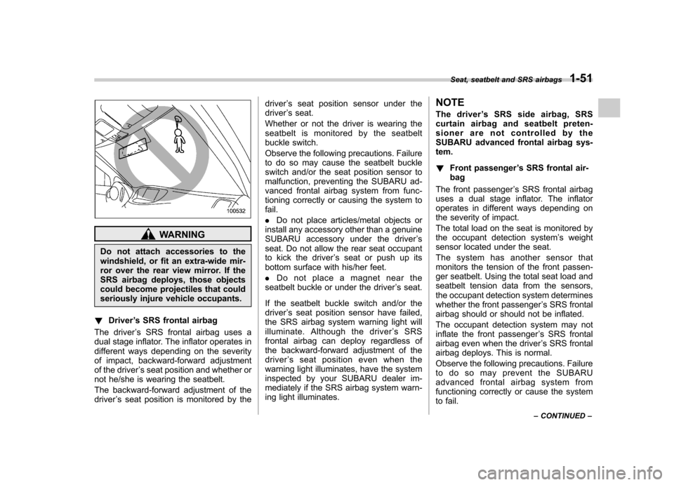
WARNING
Do not attach accessories to the
windshield, or fit an extra-wide mir-
ror over the rear view mirror. If the
SRS airbag deploys, those objects
could become projectiles that could
seriously injure vehicle occupants.
! Driver ’s SRS frontal airbag
The driver ’s SRS frontal airbag uses a
dual stage inflator. The inflator operates in
different ways depending on the severity
of impact, backward-forward adjustment
of the driver ’s seat position and whether or
not he/she is wearing the seatbelt.
The backward-forward adjustment of the driver ’s seat position is monitored by the driver
’s seat position sensor under the
driver ’s seat.
Whether or not the driver is wearing the
seatbelt is monitored by the seatbelt
buckle switch.
Observe the following precautions. Failure
to do so may cause the seatbelt buckle
switch and/or the seat position sensor to
malfunction, preventing the SUBARU ad-
vanced frontal airbag system from func-
tioning correctly or causing the system tofail. . Do not place articles/metal objects or
install any accessory other than a genuine
SUBARU accessory under the driver ’s
seat. Do not allow the rear seat occupant
to kick the driver ’s seat or push up its
bottom surface with his/her feet. . Do not place a magnet near the
seatbelt buckle or under the driver ’s seat.
If the seatbelt buckle switch and/or the driver ’s seat position sensor have failed,
the SRS airbag system warning light will
illuminate. Although the driver ’sSRS
frontal airbag can deploy regardless of
the backward-forward adjustment of the
driver ’s seat position even when the
warning light illuminates, have the system
inspected by your SUBARU dealer im-
mediately if the SRS airbag system warn-
ing light illuminates. NOTE
The driver
’s SRS side airbag, SRS
curtain airbag and seatbelt preten-
sioner are not controlled by the
SUBARU advanced frontal airbag sys-tem. ! Front passenger ’s SRS frontal air-
bag
The front passenger ’s SRS frontal airbag
uses a dual stage inflator. The inflator
operates in different ways depending on
the severity of impact.
The total load on the seat is monitored by
the occupant detection system ’s weight
sensor located under the seat.
The system has another sensor that
monitors the tension of the front passen-
ger seatbelt. Using the total seat load and
seatbelt tension data from the sensors,
the occupant detection system determines
whether the front passenger ’s SRS frontal
airbag should or should not be inflated.
The occupant detection system may not
inflate the front passenger ’s SRS frontal
airbag even when the driver ’s SRS frontal
airbag deploys. This is normal.
Observe the following precautions. Failure
to do so may prevent the SUBARU
advanced frontal airbag system from
functioning correctly or cause the system
to fail. Seat, seatbelt and SRS airbags
1-51
– CONTINUED –
Page 81 of 420

1-52Seat, seatbelt and SRS airbags
. Do not apply any strong impact to the
front passenger ’s seat such as by kicking.
. Do not spill liquid on the front passen-
ger ’s seat. If liquid is spilled, wipe it off
immediately. . Do not remove or disassemble the front
passenger ’s seat.
. Do not install any accessory (such as
an audio amplifier) other than a genuine
SUBARU accessory under the front pas-senger ’s seat.
. Do not place anything (shoes, umbrel-
la, etc.) under the front passenger ’s seat.
. The front passenger ’s seat must not be
used with the head restraint removed. . Do not leave any article including a
child restraint system on the front passen- ger ’s seat or the seatbelt tongue and
buckle engaged when you leave yourvehicle. . Do not place a magnet near the
seatbelt buckle and the seatbelt retractor.
If the seatbelt buckle switch and/or front passenger ’s occupant detection system
have failed, the SRS airbag system
warning light will illuminate. Have the
system inspected by your SUBARU deal-
er immediately if the SRS airbag system
warning light illuminates.
If your vehicle has sustained impact, this
may affect the proper function of the SUBARU advanced frontal airbag system.
Have your vehicle inspected at your
SUBARU dealer.
NOTE
The front passenger ’s SRS side airbag,
SRS curtain airbag and seatbelt pre-
tensioner are not controlled by the
SUBARU advanced frontal airbag sys-tem. ! Passenger ’s frontal airbag ON and
OFF indicators
: Front passenger ’s frontal airbag ON
indicator
: Front passenger ’s frontal airbag OFF
indicator
The front passenger ’s frontal airbag ON
and OFF indicators show you the status of
the front passenger ’s SRS frontal airbag. The indicators are located in the center
portion of the instrument panel.
When the ignition switch is turned to the “
ON ”position, both the ON and OFF
indicators illuminate for 6 seconds during
which time the system is checked. Follow-
ing the system check, both indicators turn
off for 2 seconds. After that, one of the
indicators illuminates depending on the
status of the front passenger ’s SRS frontal
airbag determined by the SUBARU ad-
vanced frontal airbag system monitoring.
If the front passenger ’s SRS frontal airbag
is activated, the passenger ’s frontal airbag
ON indicator will illuminate while the OFF
indicator will remain off.
If the front passenger ’s SRS frontal airbag
is deactivated, the passenger ’s frontal
airbag ON indicator will remain off while
the OFF indicator will illuminate.
With the ignition switch turned to the “ON ”
position, if both the ON and OFF indica-
tors simultaneously remain illuminated or
off even after the system check period, the
system is malfunctioning. Contact your
SUBARU dealer immediately for an in-spection.
Page 100 of 420
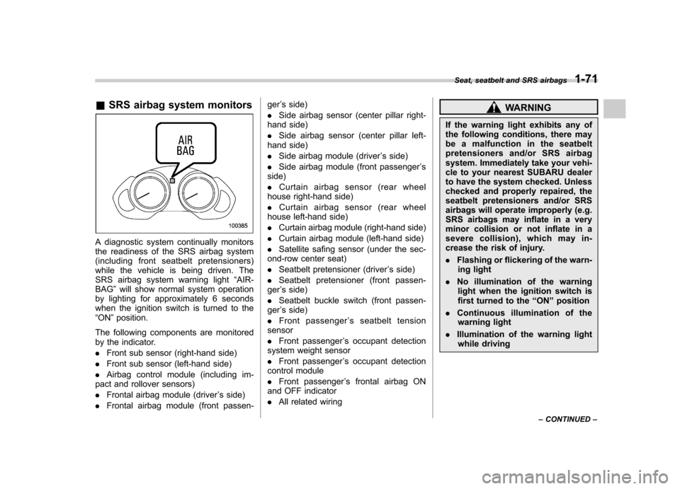
&SRS airbag system monitors
A diagnostic system continually monitors
the readiness of the SRS airbag system
(including front seatbelt pretensioners)
while the vehicle is being driven. The
SRS airbag system warning light “AIR-
BAG ”will show normal system operation
by lighting for approximately 6 seconds
when the ignition switch is turned to the“ ON ”position.
The following components are monitored
by the indicator. . Front sub sensor (right-hand side)
. Front sub sensor (left-hand side)
. Airbag control module (including im-
pact and rollover sensors). Frontal airbag module (driver ’s side)
. Frontal airbag module (front passen- ger
’s side)
. Side airbag sensor (center pillar right-
hand side). Side airbag sensor (center pillar left-
hand side). Side airbag module (driver ’s side)
. Side airbag module (front passenger ’s
side). Curtain airbag sensor (rear wheel
house right-hand side). Curtain airbag sensor (rear wheel
house left-hand side). Curtain airbag module (right-hand side)
. Curtain airbag module (left-hand side)
. Satellite safing sensor (under the sec-
ond-row center seat) . Seatbelt pretensioner (driver ’s side)
. Seatbelt pretensioner (front passen-
ger ’s side)
. Seatbelt buckle switch (front passen-
ger ’s side)
. Front passenger ’s seatbelt tension
sensor . Front passenger ’s occupant detection
system weight sensor. Front passenger ’s occupant detection
control module. Front passenger ’s frontal airbag ON
and OFF indicator. All related wiring
WARNING
If the warning light exhibits any of
the following conditions, there may
be a malfunction in the seatbelt
pretensioners and/or SRS airbag
system. Immediately take your vehi-
cle to your nearest SUBARU dealer
to have the system checked. Unless
checked and properly repaired, the
seatbelt pretensioners and/or SRS
airbags will operate improperly (e.g.
SRS airbags may inflate in a very
minor collision or not inflate in a
severe collision), which may in-
crease the risk of injury. . Flashing or flickering of the warn-
ing light
. No illumination of the warning
light when the ignition switch is
first turned to the “ON ”position
. Continuous illumination of the
warning light
. Illumination of the warning light
while driving
Seat, seatbelt and SRS airbags
1-71
– CONTINUED –
Page 106 of 420
Immobilizer
CAUTION
FCC WARNING
Changes or modifications not ex-
pressly approved by the party re-
sponsible for compliance could void
the user ’s authority to operate the
equipment.
The immobilizer system is designed to
prevent an unauthorized person from
starting the engine. Only keys registered
with your vehicle ’s immobilizer system can
be used to operate your vehicle. Even if
an unregistered key fits into the ignition
switch and can be turned to the “START ”
position, the engine will automatically stop
after several seconds.
Each immobilizer key contains a trans-
ponder in which the key ’s ID code is
stored. When a key is inserted into the
ignition switch and turned to the “ON ”
position, the transponder transmits thekey ’s ID code to the immobilizer system ’s
receiver. If the transmitted ID code
matches the ID code registered in the
immobilizer system, the system allows the
engine to be started. Since the ID code is
transmitted and acted upon almost in- stantly, the immobilizer system does not
impede normal starting of the engine.
If the engine does not start, pull out the
key once before trying again. Refer to“
Ignition switch ”F 3-3.
This device complies with Part 15 of
the FCC Rules and RSS-Gen of IC
Rules. Operation is subject to the
following two conditions: (1) this de-
vice may not cause harmful interfer-
ence, and (2) this device must accept
any interference received, including
interference that may cause undesiredoperation.
CAUTION
. Do not place the key under direct
sunlight or anywhere it may
become hot.
. Do not get the key wet. If the key
gets wet, wipe it dry with a cloth
immediately.
NOTE
To protect your vehicle from theft,
please pay close attention to the fol-
lowing security precautions. . Never leave your vehicle unattended
with its keys inside. . Before leaving your vehicle, close all windows and lock the doors and reargate..
Do not leave spare keys or any
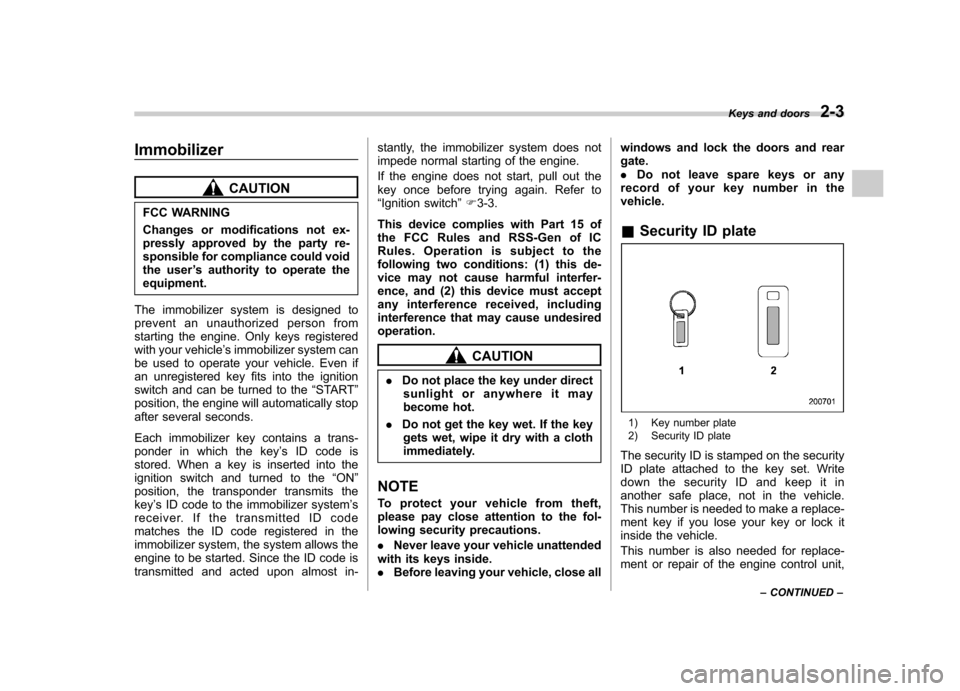
record of your key number in thevehicle. & Security ID plate
1) Key number plate
2) Security ID plate
The security ID is stamped on the security
ID plate attached to the key set. Write
down the security ID and keep it in
another safe place, not in the vehicle.
This number is needed to make a replace-
ment key if you lose your key or lock it
inside the vehicle.
This number is also needed for replace-
ment or repair of the engine control unit, Keys and doors
2-3
– CONTINUED –
Page 132 of 420

Ignition switch..................................................... 3-3
LOCK .................................................................. 3-3
Acc..................................................................... 3-4
ON...................................................................... 3-4
START ................................................................ 3-4
Key reminder chime ............................................ 3-4
Ignition switch light ............................................. 3-4
Hazard warning flasher ....................................... 3-5
Meters and gauges. ............................................. 3-5
Combination meter illumination ........................... 3-5
Canceling the function for meter needle/gauge movement and combination meter sequential
illumination upon turning on the ignition switch ............................................................... 3-5
Speedometer ....................................................... 3-6
Odometer ............................................................ 3-6
Double trip meter ................................................ 3-7
Tachometer ......................................................... 3-7
Fuel gauge .......................................................... 3-8
Temperature gauge ............................................. 3-8
Warning and indicator lights .............................. 3-9
Seatbelt warning light and chime ........................ 3-10
SRS airbag system warning light ........................ 3-11
Front passenger ’s frontal airbag ON and OFF
indicators ......................................................... 3-12
CHECK ENGINE warning light/Malfunction indicator light ................................................... 3-12
Charge warning light .......................................... 3-13
Oil pressure warning light .................................. 3-13
AT OIL TEMP warning light ................................. 3-13 Rear differential oil temperature warning
light ................................................................ 3-13
Low tire pressure warning light .......................... 3-14
ABS warning light .............................................. 3-15
Brake system warning light ................................ 3-16
Low fuel warning light ....................................... 3-17
Door open warning light .................................... 3-17
Windshield washer fluid warning light ................ 3-17
All-Wheel Drive warning light ... .......................... 3-18
Vehicle Dynamics Control warning light (U.S.- spec models and Canada-spec. models)/Vehicle
Dynamics Control operation indicator light (allmodels) ........................................................... 3-18
Traction Control system OFF indicator light (U.S.-spec models and Canada-spec.models) ........................................................... 3-19
Vehicle Dynamics Control warning light (Latin America-spec. models)/Traction Control OFF
indicator light (Latin America-spec. models) ..... 3-19
Security indicator light ....................................... 3-21
SPORT mode indicator light ............................... 3-21
Select lever/Gear position indicator .................... 3-21
Turn signal indicator lights ................................. 3-21
High beam indicator light ................................... 3-22
Cruise control indicator light .............................. 3-22
Cruise control set indicator light ........................ 3-22
Headlight indicator light ..................................... 3-22
Front fog light indicator light .............................. 3-22
Clock .................................................................. 3-22
Outside temperature indicator .......................... 3-23
Low outside temperature warning ...................... 3-24
Instruments and controls
3
Page 134 of 420
Ignition switch
WARNING
. Never turn the ignition switch to
“ LOCK ”while the vehicle is
being driven or towed because
that will lock the steering wheel,
preventing steering control. And
when the engine is turned off, it
takes a much greater effort than
usual to steer.
. Before leaving the vehicle, al-
ways remove the key from the
ignition switch for safety and
never allow an unattended child
to remain in the vehicle. Failure
to follow this procedure could
result in injury to a child or
others. Children could operate
the power windows, the moon-
roof or other controls or even
make the vehicle move.
CAUTION
Do not attach a large key holder or
key case to either key. If it banged
against your knees or hands while
you were driving, it could turn the
ignition switch from the “ON ”posi- tion to the
“Acc ”or “LOCK ”posi-
tion, thereby stopping the engine.
Also, if the key is attached to a
keyholder or to a large bunch of
other keys, centrifugal force may act
on it as the vehicle moves, resulting
in unwanted turning of the ignitionswitch.
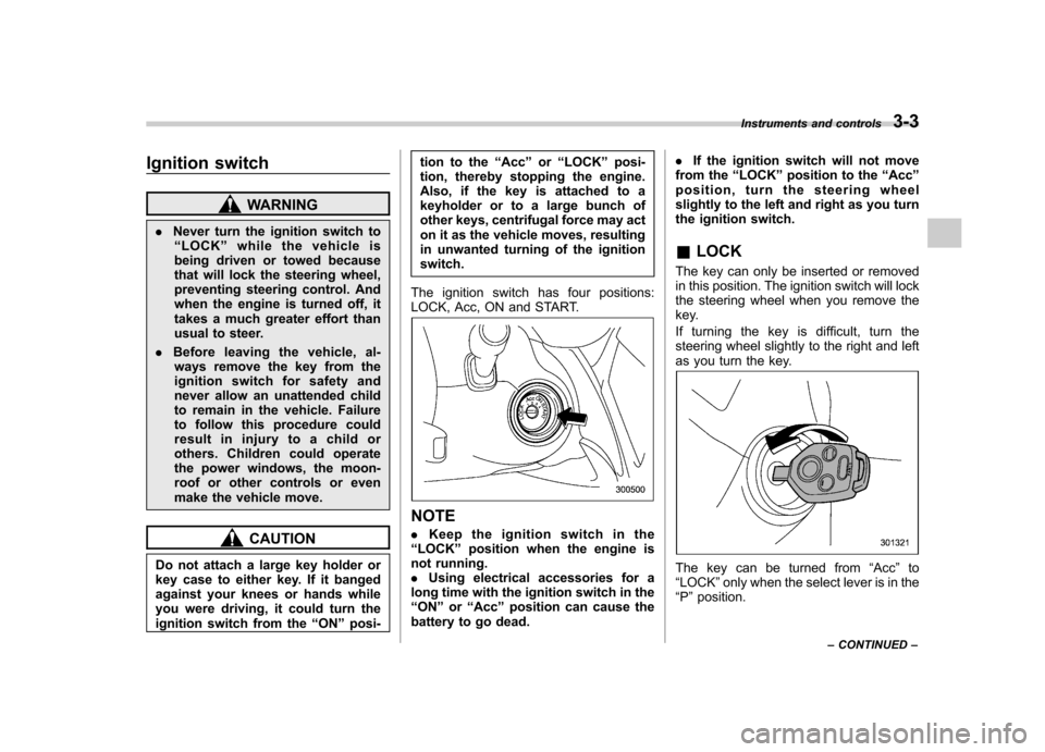
The ignition switch has four positions:
LOCK, Acc, ON and START.
NOTE . Keep the ignition switch in the
“ LOCK ”position when the engine is
not running. . Using electrical accessories for a
long time with the ignition switch in the“ ON ”or “Acc ”position can cause the
battery to go dead. .
If the ignition switch will not move
from the “LOCK ”position to the “Acc ”
position, turn the steering wheel
slightly to the left and right as you turn
the ignition switch. & LOCK
The key can only be inserted or removed
in this position. The ignition switch will lock
the steering wheel when you remove the
key.
If turning the key is difficult, turn the
steering wheel slightly to the right and left
as you turn the key.
The key can be turned from “Acc ”to
“ LOCK ”only when the select lever is in the
“ P ”position. Instruments and controls
3-3
– CONTINUED –