2012 SUBARU TRIBECA service
[x] Cancel search: servicePage 248 of 420
need to add any fuel system cleaning
agents to your fuel tank.
Many gasolines are now blended with
materials called oxygenates. Use of these
fuels can also help keep the air cleaner.
Oxygenated blend fuels, such as MTBE
(Methyl Tertiary Butyl ether) or ethanol
(ethyl or grain alcohol) may be used in
your vehicle, but should contain no more
than 15% MTBE or 10% ethanol for the
proper operation of your SUBARU.
In addition, some gasoline suppliers are
now producing reformulated gasolines,
which are designed to reduce vehicle
emissions. SUBARU approves the use of
reformulated gasoline.
If you are not sure what the fuel contains,
you should ask your service station
operators if their gasolines contain deter-
gents and oxygenates and if they have
been reformulated to reduce vehicle emis-sions.
As additional guidance, only use fuels
suited for your vehicle as explained in thefollowing. .Fuel should be unleaded and have an
octane rating no lower than that specified
in this manual. . Methanol (methyl or wood alcohol) is
sometimes mixed with unleaded gasoline. Methanol can be used in your vehicle
ONLY
if it does not exceed 5% of the fuel
mixture ANDif it is accompanied by
sufficient quantities of the proper cosol-
vents and corrosion inhibitors required to
prevent damage to the fuel system. Do not
use fuel containing methanol EXCEPT
under these conditions. . If undesirable driveability problems are
experienced and you suspect they may be
fuel related, try a different brand of gaso-
line before seeking service at your
SUBARU dealer. . Fuel system damage or driveability
problems which result from the use of
improper fuel are not covered under the
SUBARU Limited Warranty.
& Fuel filler lid and cap
! Refueling
Only one person should be involved in
refueling. Do not allow others to approach
the area of the vehicle near the fuel filler
pipe while refueling is in progress.
Be sure to observe any other precautions
that are posted at the service station.
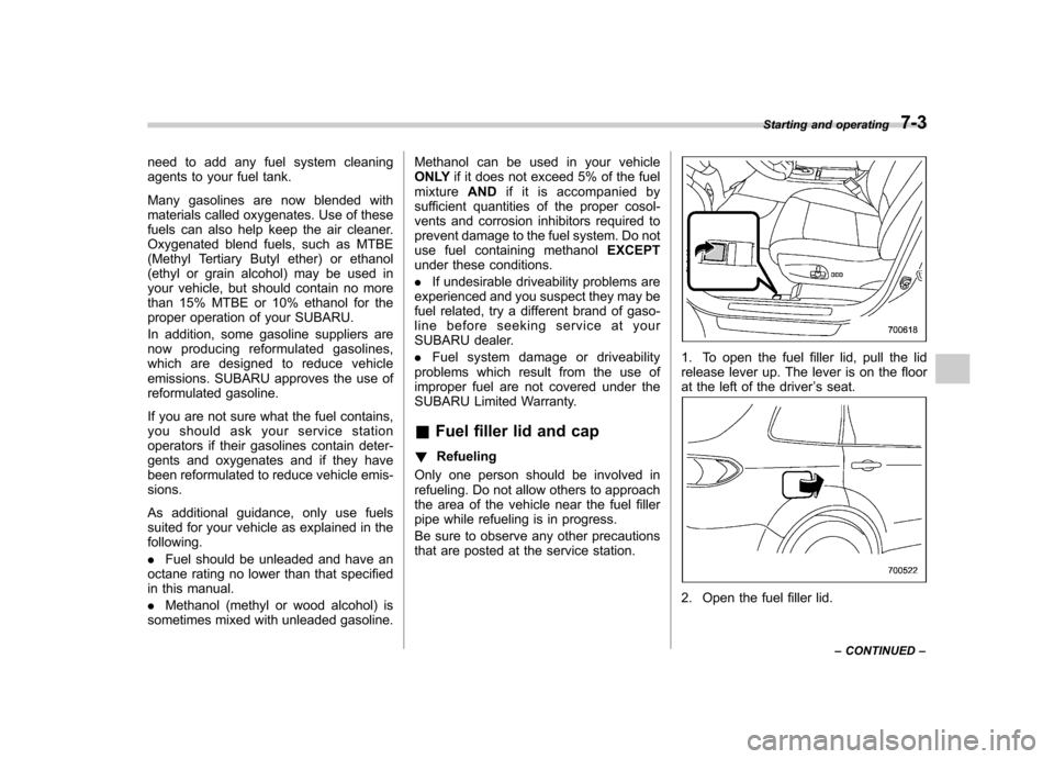
1. To open the fuel filler lid, pull the lid
release lever up. The lever is on the floor
at the left of the driver ’s seat.
2. Open the fuel filler lid. Starting and operating
7-3
– CONTINUED –
Page 250 of 420
NOTE
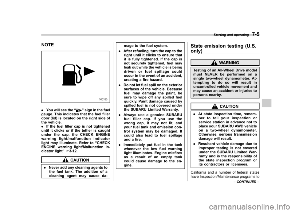
.You will see the “”sign in the fuel
gauge. This indicates that the fuel filler
door (lid) is located on the right side of
the vehicle.. If the fuel filler cap is not tightened
until it clicks or if the tether is caught
under the cap, the CHECK ENGINE
warning light/malfunction indicator
light may illuminate. Refer to “CHECK
ENGINE warning light/Malfunction in-
dicator light ”F 3-12.
CAUTION
. Never add any cleaning agents to
the fuel tank. The addition of a
cleaning agent may cause da- mage to the fuel system.
. After refueling, turn the cap to the
right until it clicks to ensure that
it is fully tightened. If the cap is
not securely tightened, fuel may
leak out while the vehicle is being
driven or fuel spillage could
occur in the event of an accident,
creating a fire hazard.
. Do not let fuel spill on the exterior
surfaces of the vehicle. Because
fuel may damage the paint, be
sure to wipe off any spilled fuel
quickly. Paint damage caused by
spilled fuel is not covered under
the SUBARU Limited Warranty.
. Always use a genuine SUBARU
fuel filler cap. If you use the
wrong cap, it may not fit, and
your fuel tank and emission con-
trol system may be damaged. It
could also lead to fuel spillage
and a fire.
. Immediately put fuel in the tank
whenever the low fuel warning
light illuminates. Engine misfires
as a result of an empty tank
could cause damage to the en-gine. State emission testing (U.S. only)
WARNING
Testing of an All-Wheel Drive model
must NEVER be performed on a
single two-wheel dynamometer. At-
tempting to do so will result in
uncontrolled vehicle movement and
may cause an accident or injuries to
persons nearby.
CAUTION
. At state inspection time, remem-
ber to tell your inspection or
service station in advance not to
place your SUBARU AWD vehicle
on a two-wheel dynamometer.
Otherwise, serious transmission
damage will result.
. Resultant vehicle damage due to
improper testing is not covered
under the SUBARU Limited War-
ranty and is the responsibility of
the state inspection program or
its contractors or licensees.
California and a number of federal states
have Inspection/Maintenance programs to Starting and operating
7-5
– CONTINUED –
Page 251 of 420

7-6Starting and operating
inspect your vehicle ’s emission control
system. If your vehicle does not pass this
test, some states may deny renewal of
your vehicle ’s registration.
Your vehicle is equipped with a computer
that monitors the performance of the engine ’s emission control system. Certi-
fied emission inspectors will inspect the
On-Board Diagnostic (OBDII) system as
part of the state emission inspection
process. The OBDII system is designed
to detect engine and transmission pro-
blems that might cause the vehicle emis-
sions to exceed allowable limits. OBDII
inspections apply to all 1996 model year
and newer passenger cars and trucks.
Over 30 states plus the District of Colum-
bia have implemented emission inspec-
tion of the OBDII system. . The inspection of the OBDII system
consists of a visual operational check of the “CHECK ENGINE ”warning light/mal-
function indicator light (MIL) and an
examination of the OBDII system with an
electronic scan tool. . A vehicle
passes the OBDII system
inspection if proper operation of the “ CHECK ENGINE ”warning light is ob-
served, there are no stored diagnostic
trouble codes, and the OBDII readiness
monitors are all complete. .
A vehicle
fails the OBDII inspection if
the “CHECK ENGINE ”warning light is not
properly operating (light is illuminated or is
not working due to a burned out bulb) or
there is one or more diagnostic trouble
codes stored in the vehicle ’s computer.
. A state emission inspection may reject
(not pass or fail) a vehicle if the number of
OBDII system readiness monitors “NOT
READY ”is greater than one. If the
vehicle ’s battery has been recently re-
placed or disconnected, the OBDII system
inspection may indicate that the vehicle is
not ready for the emission test. Under this
condition, the vehicle driver should be
instructed to drive his/her vehicle for a few
days to reset the readiness monitors and
return for an emission re-inspection. . Owners of rejected or failing vehicles
should contact their SUBARU Dealer for service.
Some states still use dynamometers in
their emission inspection program. A
dynamometer is a treadmill or roller-like
testing device that allows your vehicle ’s
wheels to turn while the vehicle remains in
one place. Prior to your vehicle being put
on a dynamometer, tell your emission
inspector
not to place your SUBARU
AWD vehicle on a two-wheel dynam-
ometer. Otherwise, serious transmis-
sion damage will result. The U.S. Environmental Protection
Agency (EPA) and states using two-wheel
dynamometers in their emission testing
program have EXEMPTED SUBARU
AWD vehicles from the portion of the
testing program that involves a two-wheel
dynamometer. There are some states that
use four-wheel dynamometers in their
testing program. When properly used, this
equipment should not damage a SUBARU
AWD vehicle.
Under no circumstances should the rear
wheels be jacked off the ground, nor
should the driveshaft be disconnected for
state emission testing.
Page 253 of 420
7-8Starting and operating
started. The fuel injection system auto-
matically lowers the idle speed as the
engine warms up.
While the engine is warming up, make
sure that the select lever is at the “P ” or
“ N ”position and that the parking brake is
applied. NOTE . The engine may be difficult to start
when the battery has been discon-
nected and reconnected (for mainte-
nance or other purposes). This diffi-
culty is caused by the electronically
controlled throttle ’s self-diagnosis
function. To overcome it, keep the
ignition switch in the “ON ”position
for approximately 10 seconds before
starting the engine.. To protect the engine while the
select lever is in the “P ” or “N ”
position, the engine is controlled so
that the engine speed may not become
too high even if the accelerator pedal is
depressed hard. Stopping the engine
WARNING
Do not stop the engine when the
vehicle is moving. This will cause
loss of power to the power steering
and the brake booster, making steer-
ing and braking more difficult. It
could also result in accidental acti-
vation of the “LOCK ”position on the
ignition switch, causing the steering
wheel to lock.
The ignition switch should be turned off
only when the vehicle is stopped and the
engine is idling. Remote engine start system
(dealer option)
WARNING
. Do not start the engine using the
remote start system in an en-
closed environment (e.g. closed
garage). Prolonged operation of
a motor vehicle in an enclosed
environment can cause a harmful
build-up of Carbon Monoxide.
Carbon Monoxide is harmful to
your health. Exposure to high
levels of Carbon Monoxide can
cause headaches, dizziness or in
extreme cases unconsciousness
and/or death.
. Before performing any servicing
of the vehicle, temporarily place
the remote engine start system in
service mode to prevent the
system from unexpectedly start-
ing the engine.
Page 255 of 420
7-10Starting and operating
transmitter within a few seconds immedi-
ately following remote engine start shut-down. & Pre-heating or pre-cooling
the interior of the vehicle
Before exiting the vehicle, set the tem-
perature controls to the desired setting
and operation. After the system starts the
vehicle, the heater or air-conditioning will
activate and heat or cool the interior to
your setting. & Service mode
In service mode, the remote start function
is temporarily disabled to prevent the
system from unexpectedly starting the
engine while being serviced. ! To engage the service mode
Turn the ignition switch to the “ON ”
position, depress and hold the brake pedal
then, press and release the “
”button on
the remote engine start transmitter three
times. The system will pause for 1 second
and then flash the parking lights and honk
the horn three times indicating that the
system is in service mode. When attempt-
ing to activate the remote start system
while in service mode, the parking lights
will flash and the horn will honk two times
and will not start. !
To disengage the service mode
Turn the ignition switch to the “ON ”
position, depress and hold the brake
pedal, then press and release the “
”
button on the remote engine start trans-
mitter three times. The system will pause
for 1 second and flash the parking lights
one time indicating that the system has
exited service mode. NOTE
When taking your vehicle in for service,
it is recommended that you inform the
service personnel that your vehicle is
equipped with a remote engine startsystem. & Remote engine start trans-
mitter programming and pro-
grammable feature option
New transmitters can be programmed to
the remote engine start system in the
event that remote engine start transmitters
are lost, stolen or damaged. The remote
engine start system also has one pro-
grammable feature that can be adjusted
for user preference.
The remote engine start system can be
programmed to either make an audible
horn chirp upon remote start activation or
not. Remote engine start transmitter pro-
gramming and feature programming can be adjusted using the following procedure.
1. Open the driver
’s door (the driver ’s
door must remain opened throughout the
entire process).
2. Insert the key into the vehicle ’s ignition
switch and turn to the “ON ”position.
3. Locate the small black programming
button behind the fuse box cover, on the
driver ’s side left under the dashboard
panel.
4. Press and hold the black programming
button for 10 to 15 seconds. The horn will
honk and the parking lights will flash three
times to indicate that the system has
entered programming mode. At this point
you can perform either action (step 5 or
step 6).
5. To program a remote transmitter:
press and release the “
”button on each
transmitter. The horn will honk and the
parking lights will flash one time to indicate
a successful transmitter learn each timethe “
”button is pressed. You can
program up to eight transmitters.
6. To toggle the Horn Confirmation chirps
ON/OFF: press and release the brake to
toggle the feature. The horn will chirp and
the parking lights will flash one time to
indicate Confirmation Horn Chirps are“ OFF ”. The horn will honk and the parking
lights will flash 2 times to indicate Con-
firmation Horn Chirps are “ON ”. Depres-
Page 281 of 420
8-4Driving tips
Periodic inspections
To keep your vehicle in the best condition
at all times, always have the recom-
mended maintenance services listed in
the maintenance schedule in the “War-
ranty and Maintenance Booklet ”per-
formed at the specified time or mileageintervals. Driving in foreign countries
When planning to use your vehicle in
another country: .
Confirm the availability of the correct
fuel. Refer to “Fuel requirements ”F 7-2.
. Comply with all regulations and re-
quirements of each country. Driving tips for AWD models
WARNING
. Always maintain a safe driving
speed according to the road and
weather conditions in order to
avoid having an accident on a
sharp turn, during sudden brak-
ing or under other similar condi-tions.
. Always use the utmost care in
driving –overconfidence be-
cause you are driving an All-
Wheel Drive model could easily
lead to a serious accident.
. When replacing a tire, you must
use a tire that is of the same size,
circumference, construction,
brand (tread pattern), speed sym-
bol and load index as the original
tires listed on the tire placard.
Using tires of other sizes, cir-
cumferences or constructions
may result in severe mechanical
damage to the drive train of your
vehicle and may affect ride,
handling, braking, speedometer/
odometer calibration, and clear-
ance between the body and tires.
It also may be dangerous and
Page 303 of 420
8-26Driving tips
blind spots occur with the vehicle ’s stan-
dard side mirrors, use towing mirrors that
conform with Federal, state/province and/
or other applicable regulations. ! Trailer lights
CAUTION
Direct splicing or other improper
connection of trailer lights may
damage your vehicle ’s electrical
system and cause a malfunction of
your vehicle ’s lighting system.
Connection of trailer lights to your vehi-cle ’s electrical system requires modifica-
tions to the vehicle ’s lighting circuit to
increase its capacity and accommodate
wiring changes. To ensure the trailer lights
are connected properly, please consult
your SUBARU dealer. Check for proper
operation of the turn signals, the brake
lights and parking lights each time you
hitch up. ! Tires
WARNING
Never tow a trailer when the tem-
porary spare tire is used. The tem-
porary spare tire is not designed to
sustain the towing load. Use of the temporary spare tire when towing
can result in failure of the spare tire
and/or less stability of the vehicle.
Make sure that all the tires on your vehicle
are properly inflated.
The recommended cold tire pressure
under trailer towing conditions is shownin “Tires ”F 12-8 and in “GAS STATION
REFERENCE ”at the end of this manual.
Adjustthereartirepressuretothe
recommended pressure when the tires
are cold. Normal pressure should be
maintained in the front tires.
Trailer tire condition, size, load rating and
proper inflation pressure should be in
accordance with the trailer manufacturer ’s
specifications.
In the event your vehicle gets a flat tire
when towing a trailer, ask a commercial
road service to repair the flat tire.
If you carry a regular size spare tire in your
vehicle or trailer as a precaution against
getting a flat tire, be sure that the spare
tire is firmly secured. &
Trailer towing tips
CAUTION
. Never exceed 45 mph (72 km/h)
when towing a trailer in hilly
country on hot days.
. When towing a trailer, steering,
stability, stopping distance and
braking performance will be dif-
ferent from normal operation. Forsafety ’s sake, you should employ
extra caution when towing a
trailer and you should never
speed. You should also keep the
following tips in mind:
! Before starting out on a trip
. Check that the vehicle and vehicle-to-
hitch mounting are in good condition. If
any problems are apparent, do not tow the
trailer. . Check that the vehicle sits horizontally
with the trailer attached. If the vehicle is
tipped sharply up at the front and down at
the rear, check the total trailer weight,
GVW, GAWs and tongue load again, then
confirm that the load and its distribution
are acceptable. . Checkthatthetirepressuresare
correct.
Page 314 of 420
WARNING
Do not use oil or grease on the
wheel studs or nuts when the spare
tire is installed. This could cause the
nuts to become loose and lead to anaccident.
15. Turn the jack handle counterclockwise
to lower the vehicle.
CAUTION
There are 2 types of wheel nut
wrenches that apply to differentlengths.
For models with silver-colored alu-
minum wheels, the 10.8-inch (275
mm) wheel nut wrench is equipped
as a maintenance tool. And for
models with optional chrome-fin-
ished wheels, the 13.2-inch (335
mm) wheel nut wrench is equipped
as well. Confirm the equipped wheel
nut wrench type when you replace a
tire. If the wheel nut wrench is the
different type, it cannot be tightened
to the specified torque.
1) The length of the wheel nut wrench
16. Confirm the length of the equipped
wheel nut wrench and wheel nut tighten-
ing torque. Refer to “Tires ”F 12-8.
17. Use the wheel nut wrench to securely
tighten the wheel nuts to the specified torque, following the tightening order in theillustration.
Never use your foot on the wheel nut
wrench or a pipe extension on the wrench
because you may exceed the specified
torque. Have the wheel nut torque
checked at the nearest automotive service
facility.
WARNING
Do not use the extension when
turning the wheel nuts. If you did,
you would not be able to achieve
sufficient tightening torque. The
wheel nuts could then come loose,
resulting in a serious accident.
18. Store the flat tire in the spare tire In case of emergency
9-9
– CONTINUED –