2012 SUBARU TRIBECA ECO mode
[x] Cancel search: ECO modePage 170 of 420
Gear
position Period of
time multi-
function
button is pressed Function
displayed
R (reverse) Briefly
Rear view display ON/OFF*
More than
3 seconds Help lines indica-
tion ON/OFF
Except
R (reverse) Briefly
Auto-dimming
function ON/OFF*
3to6 seconds Electronic com-
pass display ON/ OFF
6to9seconds Enter the com-
pass zone setting mode
9to12 seconds Enter the com-
pass calibration mode
*: The setting returns to “ON ”as a default
setting every time the ignition switch is turned tothe “ON ”position.
! Rear view image display
When the ignition switch is “ON ”and the
select lever is set to “R ”, the rear view
camera automatically displays the rear
view image behind the vehicle on the
inside mirror.
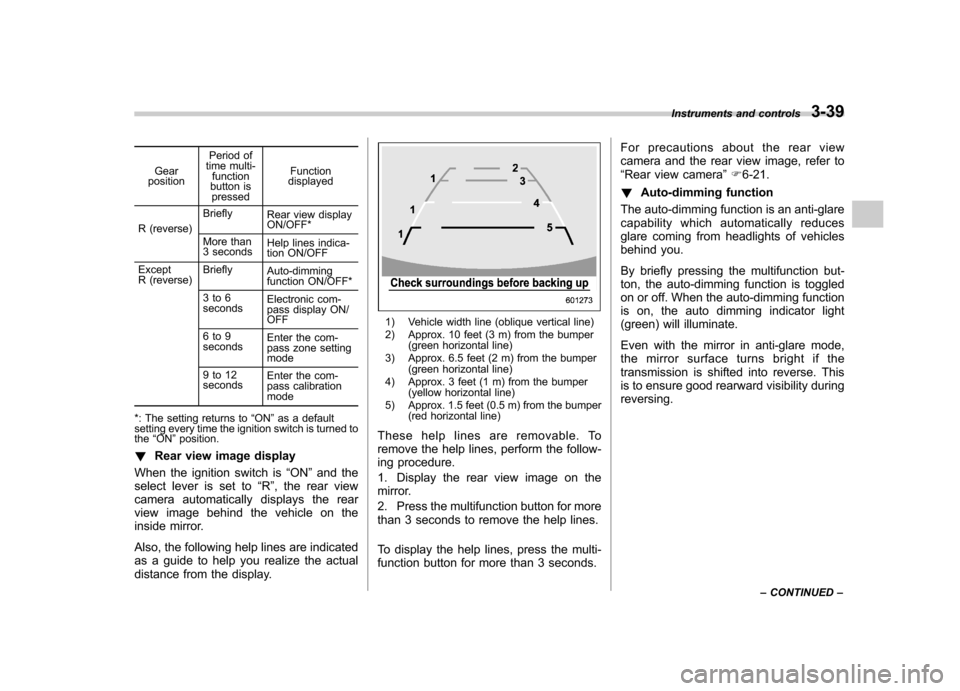
Also, the following help lines are indicated
as a guide to help you realize the actual
distance from the display.
1) Vehicle width line (oblique vertical line)
2) Approx. 10 feet (3 m) from the bumper (green horizontal line)
3) Approx. 6.5 feet (2 m) from the bumper (green horizontal line)
4) Approx. 3 feet (1 m) from the bumper (yellow horizontal line)
5) Approx. 1.5 feet (0.5 m) from the bumper (red horizontal line)
These help lines are removable. To
remove the help lines, perform the follow-
ing procedure.
1. Display the rear view image on the
mirror.
2. Press the multifunction button for more
than 3 seconds to remove the help lines.
To display the help lines, press the multi-
function button for more than 3 seconds. For precautions about the rear view
camera and the rear view image, refer to“
Rear view camera ”F 6-21.
! Auto-dimming function
The auto-dimming function is an anti-glare
capability which automatically reduces
glare coming from headlights of vehicles
behind you.
By briefly pressing the multifunction but-
ton, the auto-dimming function is toggled
on or off. When the auto-dimming function
is on, the auto dimming indicator light
(green) will illuminate.
Even with the mirror in anti-glare mode,
the mirror surface turns bright if the
transmission is shifted into reverse. This
is to ensure good rearward visibility duringreversing. Instruments and controls
3-39
– CONTINUED –
Page 171 of 420
3-40Instruments and controls
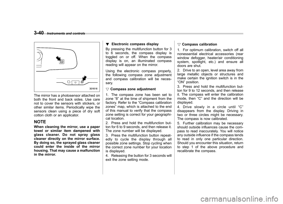
The mirror has a photosensor attached on
both the front and back sides. Use care
not to cover the sensors with stickers, or
other similar items. Periodically wipe the
sensors clean using a piece of dry soft
cotton cloth or an applicator. NOTE
When cleaning the mirror, use a paper
towel or similar item dampened with
glass cleaner. Do not spray glass
cleaner directly on the mirror surface.
By doing so, the sprayed glass cleaner
could enter the inside of the mirror
housing. That may cause a malfunction
in the mirror. !
Electronic compass display
By pressing the multifunction button for 3
to 6 seconds, the compass display is
toggled on or off. When the compass
display is on, an illuminated compass
reading will appear on the mirror.
Using the electronic compass properly,
the following compass zone adjustment
and compass calibration will be neces-
sary. ! Compass zone adjustment
1. The compass zone has been set to zone “8 ” at the time of shipment from the
factory. Refer to the “Compass calibration
zones ”map, which is attached to the end
of this manual to verify that the compass
zone setting is correct for your geographi-
cal location.
2. Press and hold the multifunction but-
ton for 6 to 9 seconds, and then release it.
The zone number will be displayed.
3. Press the multifunction button repeat-
edly to cycle the display through all
possible zone settings. Stop cycling when
the correct zone number for your location
is displayed.
4. Releasing the button for 3 seconds will
exit the zone setting mode. !
Compass calibration
1. For optimum calibration, switch off all
nonessential electrical accessories (rear
window defogger, heater/air conditioning
system, spotlight, etc.) and ensure all
doors are shut.
2. Drive to an open, level area away from
large metallic objects or structures and
make certain the ignition switch is in the“ ON ”position.
3. Press and hold the multifunction but-
ton for 9 to 12 seconds, and then release
it. The compass will enter the calibration
mode, then “C ” and the direction will be
displayed.
4. Drive slowly in a circle until “C ”
disappears from the display. Driving in
two or three circles might be necessary.
The compass is now calibrated.
5. Further calibration may be necessary
should outside influences cause the com-
pass to read inaccurately. You will notice
any outside influence if the compass tends
to read in only one particular direction.
Should you encounter this situation, return
to step 1 of the above procedure and
recalibrate the compass.
Page 172 of 420

&Type C inside mirror (if equipped)
1) Left button
2) Auto dimming indicator
3) Photosensor
4) Right button
This mirror has an anti-glare feature which
automatically reduces glare coming from
headlights of vehicles behind you. It also
contains a built-in compass. . By pressing and releasing the left
button, the automatic dimming function is
toggled on or off. When the automatic
dimming function is on, the auto dimming
indicator light (green) located to the right
of the button will illuminate. . By pressing and releasing the right
button, the compass display is toggled on or off. When the compass is on, an
illuminated compass reading will appear
in the lower part of the mirror.
Even with the mirror in anti-glare mode,
the mirror surface turns bright if the
transmission is shifted into reverse. This
is to ensure good rearward visibility duringreversing. !
Photosensors
The mirror has a photosensor attached on
both the front and back sides. If the glare
from the headlights of vehicles behind you
strikes the mirror, these sensors detect it
and make the reflection surface of the
mirror dimmer to help prevent you from
being blinded. For this reason, use care
not to cover the sensors with stickers, or
other similar items. Periodically wipe the sensors clean using a piece of dry soft
cotton cloth or an applicator. !
Compass calibration
1. For optimum calibration, switch off all
nonessential electrical accessories (rear
window defogger, heater/air conditioning
system, spotlight, etc.) and ensure all
doors are shut.
2. Drive to an open, level area away from
large metallic objects or structures and
make certain the ignition switch is in the“ ON ”position.
3. Press and hold the left button for 3
seconds then release, and the compass
will enter the calibration mode. “CAL ”and
direction will be displayed.
4. Drive slowly in a circle until “CAL ”
disappears from the display (approxi-
mately two or three circles). The compass
is now calibrated.
5. Further calibration may be necessary
should outside influences cause the mirror
to read inaccurately. You will know that
this has occurred if your compass begins
to read in only limited directions. Should
you encounter this situation, return to step
one of the above procedure and recali-
brate the mirror. Instruments and controls
3-41
– CONTINUED –
Page 173 of 420
3-42Instruments and controls
!Compass zone adjustment
1. The zone setting is factory preset to
Zone 8. Refer to the “Compass calibration
zone ”map attached to the end of this
manual to verify that the compass zone
setting is correct for your geographical location.
2. Press and hold the right button for 3
seconds then release, and the word“ ZONE ”will briefly appear and then the
zone number will be displayed.
3. Press the right-hand button repeatedly
to cycle the display through all possible
zone settings. Stop cycling when the
correct zone setting for your location isdisplayed.
4. Releasing the button for 3 seconds will
exit the zone setting mode. &
Outside mirrors
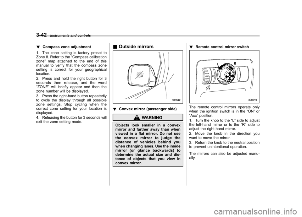
! Convex mirror (passenger side)
WARNING
Objects look smaller in a convex
mirror and farther away than when
viewed in a flat mirror. Do not use
the convex mirror to judge the
distance of vehicles behind you
when changing lanes. Use the inside
mirror (or glance backwards) to
determine the actual size and dis-
tance of objects that you view in
convex mirror. !
Remote control mirror switch
The remote control mirrors operate only
when the ignition switch is in the “ON ”or
“ Acc ”position.
1. Turn the knob to the “L ” side to adjust
the left-hand mirror or to the “R ” side to
adjust the right-hand mirror.
2. Move the knob in the direction you
want to move the mirror.
3. Return the knob to the neutral position
to prevent unintentional operation.
The mirrors can also be adjusted manu-
ally.
Page 174 of 420
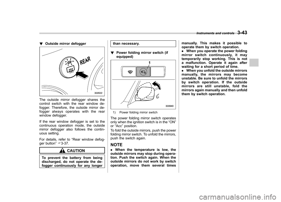
!Outside mirror defogger
The outside mirror defogger shares the
control switch with the rear window de-
fogger. Therefore, the outside mirror de-
fogger always operates with the rear
window defogger.
If the rear window defogger is set to the
continuous operation mode, the outside
mirror defogger also follows the contin-
uous setting.
For details, refer to “Rear window defog-
ger button ”F 3-37.
CAUTION
To prevent the battery from being
discharged, do not operate the de-
fogger continuously for any longer than necessary.
! Power folding mirror switch (ifequipped)
1) Power folding mirror switch
The power folding mirror switch operates
only when the ignition switch is in the “ON ”
or “Acc ”position.
To fold the outside mirrors, push the power
folding mirror switch. To unfold the mirrors,
push the switch again.
NOTE . When the temperature is low, the
outside mirrors may stop during opera-
tion. Push the switch again. When the
outside mirrors do not work by switch
operation, move them several times manually. This makes it possible to
operate them by switch operation..
When you operate the power folding
mirror switch continuously, it may
temporarily stop working. This is not
a malfunction. Operate it again after
waiting for a short period of time.. When you unfold the outside mirrors
manually, the mirrors may become
unstable. Be sure to unfold the mirrors
by switch operation. If the outside
mirrors are still unstable, fold the
mirrors again manually and then unfold
them by switch operation. Instruments and controls
3-43
Page 184 of 420
to the OFF position as soon as the
outside dusty condition clears.
NOTE
When driving on a dusty road or behind
a vehicle that emits unpleasant exhaust
gases, set the air inlet selection button
to the ON position.
From time to time, return the air inlet
selection button to the OFF position to
draw outside air into the passengercompartment. &
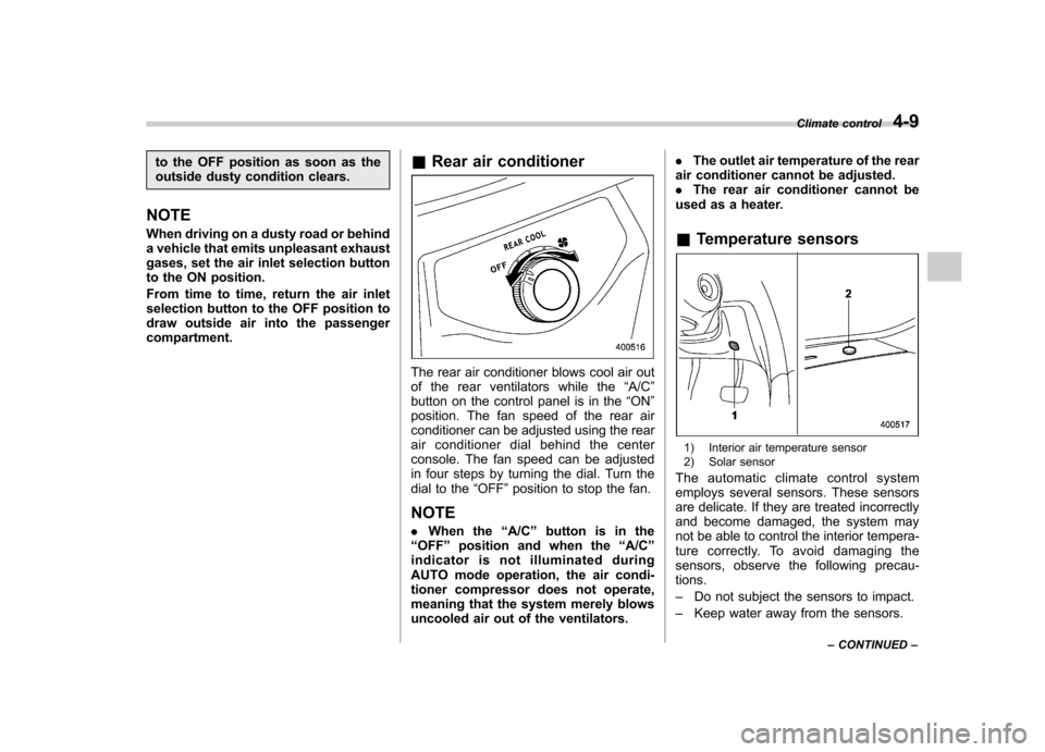
Rear air conditioner
The rear air conditioner blows cool air out
of the rear ventilators while the “A/C ”
button on the control panel is in the “ON ”
position. The fan speed of the rear air
conditioner can be adjusted using the rear
air conditioner dial behind the center
console. The fan speed can be adjusted
in four steps by turning the dial. Turn the
dial to the “OFF ”position to stop the fan.
NOTE . When the “A/C ”button is in the
“ OFF ”position and when the “A/C ”
indicator is not illuminated during
AUTO mode operation, the air condi-
tioner compressor does not operate,
meaning that the system merely blows
uncooled air out of the ventilators. .
The outlet air temperature of the rear
air conditioner cannot be adjusted.. The rear air conditioner cannot be
used as a heater. & Temperature sensors
1) Interior air temperature sensor
2) Solar sensor
The automatic climate control system
employs several sensors. These sensors
are delicate. If they are treated incorrectly
and become damaged, the system may
not be able to control the interior tempera-
ture correctly. To avoid damaging the
sensors, observe the following precau-tions. – Do not subject the sensors to impact.
– Keep water away from the sensors. Climate control
4-9
– CONTINUED –
Page 193 of 420
5-4Audio
Type A audio set (if equipped)
The audio set will operate only when the ignition switch is in the “Acc ”or “ON ”position.
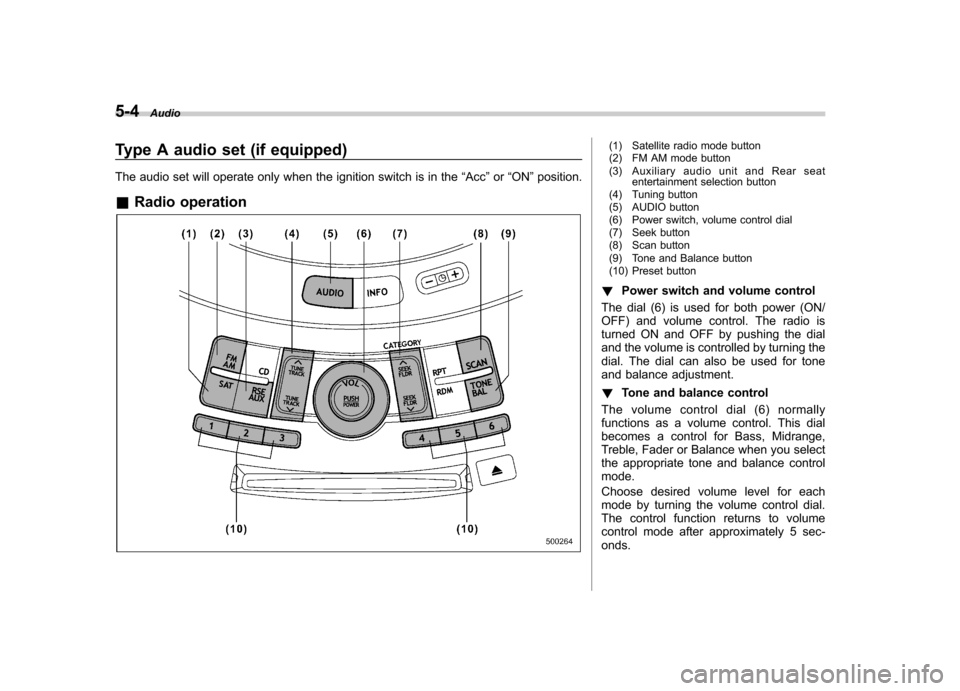
& Radio operation(1) Satellite radio mode button
(2) FM AM mode button
(3) Auxiliary audio unit and Rear seat
entertainment selection button
(4) Tuning button
(5) AUDIO button
(6) Power switch, volume control dial
(7) Seek button
(8) Scan button
(9) Tone and Balance button
(10) Preset button
! Power switch and volume control
The dial (6) is used for both power (ON/
OFF) and volume control. The radio is
turned ON and OFF by pushing the dial
and the volume is controlled by turning the
dial. The dial can also be used for tone
and balance adjustment. ! Tone and balance control
The volume control dial (6) normally
functions as a volume control. This dial
becomes a control for Bass, Midrange,
Treble, Fader or Balance when you select
the appropriate tone and balance controlmode.
Choose desired volume level for each
mode by turning the volume control dial.
The control function returns to volume
control mode after approximately 5 sec-onds.
Page 196 of 420

NOTE
While you are holding down either side
of the“TUNE TRACK ”button, the
tuning frequency will not stop chan-
ging even if the frequency of a recei-
vable station is reached. ! Seek tuning
If you press the “
”or “”side of the
“ SEEK FLDR ”button (7), the radio will
automatically search for a receivable
station and stop at the first one it finds.
This function may not be available, how-
ever, when radio signals are weak. In such
a situation, perform manual tuning to
select the desired station. ! Automatic tuning (SCAN)
Press the “SCAN ”button (8) to change the
radio to the SCAN mode. In this mode, the
radio scans through the radio band until a
station is found. The radio will stop at the
station for 5 seconds while displaying the
frequency, after which scanning will con-
tinue until the entire band has been
scanned from the low end to the high
end. Press the “SCAN ”button again to
cancel the SCAN mode and to stop on any
displayed frequency.
Press the “
”or “”side of the “SEEK
FLDR ”button (7) again to cancel the scan
mode and to stop on any displayed frequency.
When the
“SCAN ”button is pressed for
automatic tuning, stations are scanned in
the direction of low frequencies to high
frequencies only.
Automatic tuning may not function prop-
erly if the station reception is weakened by
distance from the station or proximity to
tall buildings and hills. ! Selecting preset stations
Presetting a station with a preset button
(10) allows you to select that station in a
single operation. Up to six, AM, FM1 and
FM2 stations each may be preset. ! How to preset stations
1. Press the “FM AM ”button (2) to select
FM1, FM2, or AM reception.
2. Press the “SCAN ”button (8) or tune
the radio manually until the desired station
frequency is displayed.
3. Press and hold one of the preset
buttons (10) to store the frequency. If the
button is pressed briefly, the preceding
selection will remain in memory. NOTE . If the connection between the radio
and battery is broken for any reason
such as vehicle maintenance or radio
removal, all stations stored in the preset buttons are cleared. If this
occurs, it is necessary to reset the
preset buttons..
If a cell phone is placed near the
radio, it may cause the radio to emit
noise when it receives calls. This noise
does not indicate a radio malfunction. ! Satellite radio mode (if equipped)
To receive satellite radio, it is necessary to
install the SUBARU genuine satellite
receiver (optional part) and to enter into
a contract with a satellite radio network
service such as “Sirius XM
TMsatellite
radio ”(for U.S.A. only) or “Sirius satellite
radio ”(for Canada only). For details,
please contact your SUBARU dealer. ! Sirius satellite radio (for Canada only)
Sirius satellite radio is a recent innovation
that allows the listener to experience
digital sound quality and to have a greater
variety of channels.
Use of satellite radio (Sirius) requires a
tuner, antenna and a service contract. For
details, please contact your SUBARU
dealer or visit Sirius Satellite Radio at
www.sirius.ca or call 1-888-539-7474 for
more information. Sirius, the Sirius dog
logo, channel names and logos are trade-
marks of SIRIUS Satellite Radio Inc. Audio
5-7
– CONTINUED –