2012 SUBARU IMPREZA WRX transmission
[x] Cancel search: transmissionPage 6 of 416

&Abbreviation list
You will find several abbreviations in this
manual. The meanings of the abbrevia-
tions are shown in the following list.
Abbreviation Meaning
A/C Air conditioner A/ELR Automatic/Emergency locking retractor
ABS Anti-lock brake system
AKI Anti knock index
ALR Automatic locking retractor
AT Automatic transmission
ATF Automatic transmission fluid
AWD All-wheel drive DCCD Driver
’s control center differ-
ential
DRL Daytime running lightEBD Electronic brake force distri- bution
ELR Emergency locking retractor
FWD Front-wheel drive
GAW Gross axle weight
GAWR Gross axle weight rating
GVW Gross vehicle weight
GVWR Gross vehicle weight rating
HID High intensity discharge Abbreviation Meaning
INT Intermittent
LATCH Lower anchors and tethers for
children
LED Light emitting diode
LSD Limited slip differential
MIL Malfunction indicator light MMT Methylcyclopentadienyl man-
ganese tricarbonyl
MT Manual transmission
OBD On-board diagnostics
RON Research octane number
SI-DRIVE SUBARU Intelligent Drive SRS Supplemental restraint sys- tem
TIN Tire identification number TPMS Tire pressure monitoring sys- tem
VDC Vehicle dynamics control Vehicle symbols
There are some of the symbols you may
see on your vehicle.
For warning and indicator lights, refer to “
Warning and indicator lights ”F 22.
Mark Name
WARNING
CAUTION
Power door lock
Power door unlock
Power window with automatic
open and close function
Passengers ’windows lock
and unlock
Fuel
Front fog lights 3
– CONTINUED –
Page 154 of 416
Mirrors
Always check that the inside and outside
mirrors are properly adjusted before you
start driving. &Inside mirror
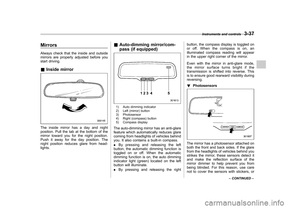
The inside mirror has a day and night
position. Pull the tab at the bottom of the
mirror toward you for the night position.
Push it away for the day position. The
night position reduces glare from head-lights. &
Auto-dimming mirror/com-
pass (if equipped)
1) Auto dimming indicator
2) Left (mirror) button
3) Photosensor
4) Right (compass) button
5) Compass display
The auto-dimming mirror has an anti-glare
feature which automatically reduces glare
coming from headlights of vehicles behind
you. It also contains a built-in compass. . By pressing and releasing the left
button, the automatic dimming function is
toggled on or off. When the automatic
dimming function is on, the auto dimming
indicator light (green) located on the left
button will illuminate. . By pressing and releasing the right button, the compass display is toggled on
or off. When the compass is on, an
illuminated compass reading will appear
in the upper right corner of the mirror.
Even with the mirror in anti-glare mode,
the mirror surface turns bright if the
transmission is shifted into reverse. This
is to ensure good rearward visibility duringreversing. !
Photosensors
The mirror has a photosensor attached on
both the front and back sides. If the glare
from the headlights of vehicles behind you
strikes the mirror, these sensors detect it
and make the reflection surface of the
mirror dimmer to help prevent you from
being blinded. For this reason, use care
not to cover the sensors with stickers, or Instruments and controls
3-37
– CONTINUED –
Page 156 of 416
dimming function is on, the LED indicator
will illuminate.
Even with the mirror in the automatic
dimming mode, the mirror surface turns
bright if the transmission is shifted into
reverse. This is to ensure good rearward
visibility during reversing. .By pressing the compass display but-
ton, the compass display is toggled on or
off. When the compass is on, an illumi-
nated compass reading will appear in the
upper right corner of the mirror.
When cleaning the mirror, use a paper
towel or similar material dampened with
glass cleaner. Do not spray glass cleaner
directly on the mirror as that may cause
theliquidcleanertoenterthemirror
housing and damage the mirror. !
Photosensors
The mirror has a photosensor attached on
both the front and back sides. During
nighttime driving, these sensors detect
distracting glare from vehicle headlights
behind you and automatically dim the
mirror to eliminate glare and preserve
your vision. For this reason, use care not
to cover the sensors with stickers, or other
similar items. Periodically wipe the sen-
sors clean using a piece of dry soft cotton
cloth or an applicator. !
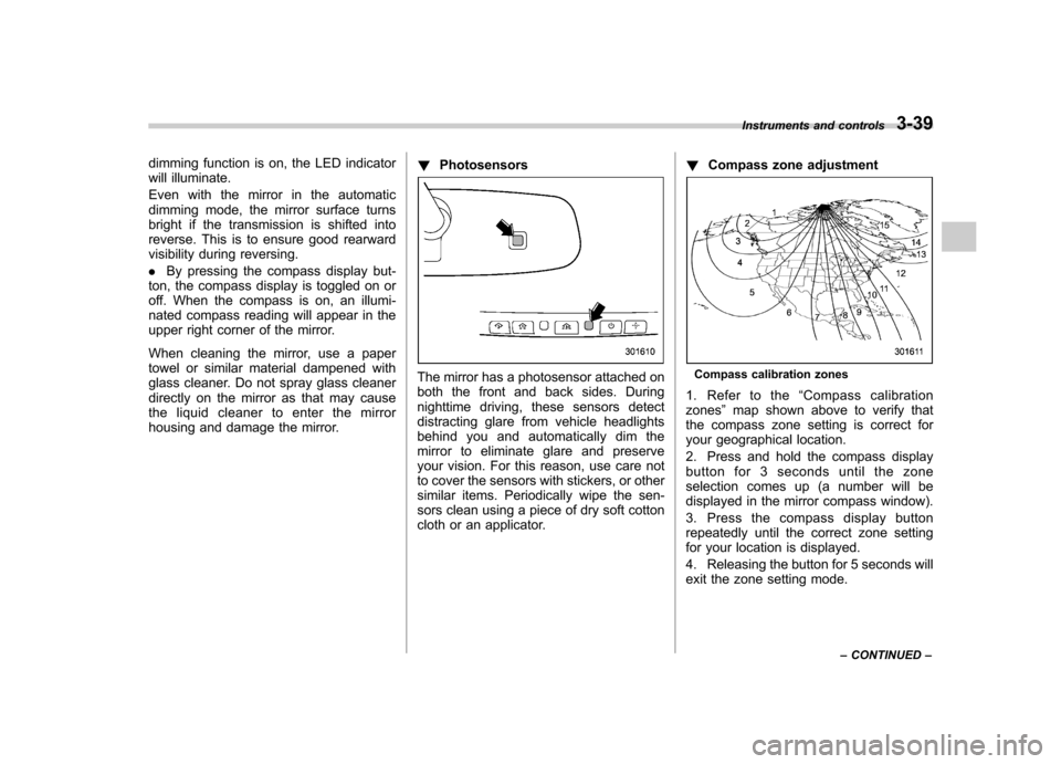
Compass zone adjustmentCompass calibration zones
1. Refer to the “Compass calibration
zones ”map shown above to verify that
the compass zone setting is correct for
your geographical location.
2. Press and hold the compass display
button for 3 seconds until the zone
selection comes up (a number will be
displayed in the mirror compass window).
3. Press the compass display button
repeatedly until the correct zone setting
for your location is displayed.
4. Releasing the button for 5 seconds will
exit the zone setting mode. Instruments and controls
3-39
– CONTINUED –
Page 211 of 416

5-30Audio
iPod
®. It randomly repeats all of the
tracks on the iPod®.
. When an iPod®is connected, the
files are played back at random by the
shuffle function of the iPod
®. There-
fore, iPod®operation may be different
depending on the model of the con-
nected iPod
®.
. When an audiobook or a podcast is
playing, the mode does not change
even if you press and hold the
button.
To cancel the random playback mode,
press and hold the
button and select
CANCEL. The “RDM ”indication will turn
off, and the normal playback mode will resume. & SCAN (only when connecting
USB storage device)
Scan is operated in the same way as for a
CD. For details, refer to “Scan ”F 5-20.
NOTE
When an iPod
®is connected, you
cannot select the SCAN mode.
& Selecting category (only
when connecting iPod
®)
When the
button is pressed briefly,
the iPod®menu is displayed. Each time you turn the
“TUNE/TRACK/
CH ”dial clockwise, the displayed category
changes in the following sequence. Each
time you turn the “TUNE/TRACK/CH ”dial
counterclockwise, the displayed category
changes in the opposite sequence.
To select the category, press the “TUNE/
TRACK/CH ”dial. To close the iPod®
menu, press and hold thebutton.
To return to the previous screen, briefly
press the
button.
& Display selection
Refer to “Display selection ”F 5-21.
! Page scroll
Refer to “Page (track/folder title) scroll ”
F 5-21.
& Folder selection (only when
connecting USB storage de- vice)
Refer to “Folder selection ”F 5-21. NOTE
When an iPod
®is connected, you
cannot select a folder. & When “CHECK DEVICE ”is
displayed
This message is displayed under the
following conditions. . When there is a short in the USB bus
. When an unsupported device (for ex-
ample a USB mouse) is connected. When an unsupported iPod
®is con-
nected . When a connected iPod
®is frozen
. When a transmission malfunction oc-
curs . When an iPod
®confirmation malfunc-
tion occurs. When a HUB class USB storage
device is connected
Disconnect the USB storage device/iPod
®
and check it.
Page 244 of 416
Fuel...................................................................... 7-3
Fuel requirements ............................................... 7-3
Fuel filler lid and cap ........................................... 7-4
State emission testing (U.S. only) ...................... 7-7
Preparing to drive ............................................... 7-8
Starting the engine .............................................. 7-9
Stopping the engine ........................................... 7-10
Remote engine start system (dealer option) .............................................................. 7-10
Starting your vehicle .......................................... 7-10
Remote start safety features ............................... 7-11
Entering the vehicle while it is running via remote start ................................................................. 7-11
Entering the vehicle following remote engine start shutdown ......................................................... 7-11
Pre-heating or pre-cooling the interior of the vehicle ............................................................. 7-11
Service mode ..................................................... 7-11
Remote engine start transmitter programming and programmable feature option ..................... 7-12
System maintenance .......................................... 7-12
Manual transmission –6 speeds (STI) ............. 7-14
Selecting reverse gear ........................................ 7-15
Shifting speeds .................................................. 7-15
Driving tips ........................................................ 7-16
Manual transmission –5 speeds (except
STI) ................................................................... 7-16
Shifting speeds .................................................. 7-17
Driving tips ........................................................ 7-17
Driver ’s Control Center Differential (DCCD)
(STI) .................................................................. 7-18 To change mode of driver
’s control center
differential ....................................................... 7-18
Auto mode ........................................................ 7-19
Manual mode ..................................................... 7-20
Temporary release ............................................. 7-21
SI-DRIVE (STI) .................................................... 7-22
Intelligent (I) mode ............................................. 7-22
Sport (S) mode .................................................. 7-22
Sport Sharp (S#) mode. ...................................... 7-23
SI-DRIVE selector .............................................. 7-23
Limited slip differential (LSD) (STI) .................. 7-24
Power steering ................................................... 7-24
Braking ............................................................... 7-24
Braking tips ....................................................... 7-24
Brake system .................................................... 7-25
Disc brake pad wear warning indicators ............. 7-25
ABS (Anti-lock Brake System) .......................... 7-26
ABS system self-check ...................................... 7-26
ABS warning light .............................................. 7-26
Electronic Brake Force Distribution (EBD) system ............................................................. 7-26
Steps to take if EBD system malfunctions ..... ..... 7-27
Vehicle Dynamics Control system .................... 7-28
Vehicle Dynamics Control system monitor..... ..... 7-29
Vehicle Dynamics Control mode switch (STI) . ..... 7-29
Vehicle Dynamics Control OFF switch (except STI) ................................................................. 7-30
Tire pressure monitoring system (TPMS) (U.S.-spec. models). ........................................ 7-32
Parking your vehicle ......................................... 7-33
Starting and operating
7
Page 250 of 416
whenever the low fuel warning
light illuminates. Engine misfires
as a result of an empty tank
could cause damage to the en-gine.State emission testing (U.S. only)
WARNING
Testing of an All-Wheel Drive model
must NEVER be performed on a
single two-wheel dynamometer. At-
tempting to do so will result in
uncontrolled vehicle movement and
may cause an accident or injuries to
persons nearby.
CAUTION
. At state inspection time, remem-
ber to tell your inspection or
service station in advance not to
place your SUBARU AWD vehicle
on a two-wheel dynamometer.
Otherwise, serious transmission
damage will result.
. Resultant vehicle damage due to
improper testing is not covered
under the SUBARU Limited War-
ranty and is the responsibility of
the state inspection program or
its contractors or licensees.
California and a number of federal states
have Inspection/Maintenance programs to inspect your vehicle
’s emission control
system. If your vehicle does not pass this
test, some states may deny renewal of
your vehicle ’s registration.
Your vehicle is equipped with a computer
that monitors the performance of the engine ’s emission control system. Certi-
fied emission inspectors will inspect the
On-Board Diagnostic (OBDII) system as
part of the state emission inspection
process. The OBDII system is designed
to detect engine and transmission pro-
blems that might cause the vehicle emis-
sions to exceed allowable limits. OBDII
inspections apply to all 1996 model year
and newer passenger cars and trucks.
Over 30 states plus the District of Colum-
bia have implemented emission inspec-
tion of the OBDII system. . The inspection of the OBDII system
consists of a visual operational check of the “CHECK ENGINE ”warning light/mal-
function indicator light (MIL) and an
examination of the OBDII system with an
electronic scan tool. . A vehicle
passes the OBDII system
inspection if proper operation of the “ CHECK ENGINE ”warning light is ob-
served, there are no stored diagnostic
trouble codes, and the OBDII readiness
monitors are all complete. Starting and operating
7-7
– CONTINUED –
Page 257 of 416
7-14Starting and operating
pressly approved by the party re-
sponsible for compliance could void
the user ’s authority to operate the
equipment.
NOTE
This device complies with Part 15 of
the FCC Rules and RSS-Gen of IC
Rules. Operation is subject to the
following two conditions: (1) this de-
vice may not cause harmful interfer-
ence, and (2) this device must accept
any interference received, including
interference that may cause undesiredoperation. Manual transmission
–6
speeds (STI)
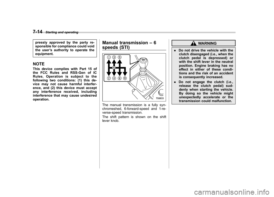
The manual transmission is a fully syn-
chromeshed, 6-forward-speed and 1-re-
verse-speed transmission.
The shift pattern is shown on the shift
lever knob.
WARNING
. Do not drive the vehicle with the
clutch disengaged (i.e., when the
clutch pedal is depressed) or
with the shift lever in the neutral
position. Engine braking has no
effect in either of these condi-
tions and the risk of an accident
is consequently increased.
. Do not engage the clutch (i.e.,
release the clutch pedal) sud-
denly when starting the vehicle.
By doing so the vehicle might
unexpectedly accelerate or the
transmission could malfunction.
Page 258 of 416
&Selecting reverse gear
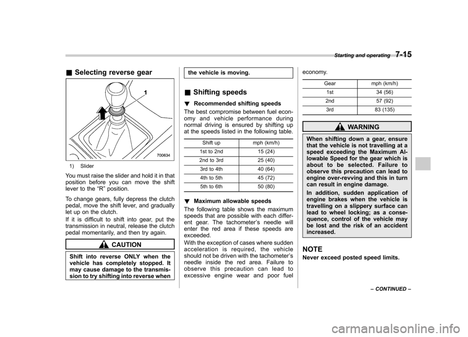
1) Slider
You must raise the slider and hold it in that
position before you can move the shift
lever to the “R ”position.
To change gears, fully depress the clutch
pedal, move the shift lever, and gradually
let up on the clutch.
If it is difficult to shift into gear, put the
transmission in neutral, release the clutch
pedal momentarily, and then try again.
CAUTION
Shift into reverse ONLY when the
vehicle has completely stopped. It
may cause damage to the transmis-
sion to try shifting into reverse when the vehicle is moving.
& Shifting speeds
! Recommended shifting speeds
The best compromise between fuel econ-
omy and vehicle performance during
normal driving is ensured by shifting up
at the speeds listed in the following table.
Shift up mph (km/h)
1st to 2nd 15 (24)
2nd to 3rd 25 (40)
3rd to 4th 40 (64)4th to 5th 45 (72)
5th to 6th 50 (80)
! Maximum allowable speeds
The following table shows the maximum
speeds that are possible with each differ-
ent gear. The tachometer ’s needle will
enter the red area if these speeds areexceeded.
With the exception of cases where sudden
acceleration is required, the vehicle
should not be driven with the tachometer ’s
needle inside the red area. Failure to
observe this precaution can lead to
excessive engine wear and poor fuel economy.
Gear mph (km/h)1st 34 (56)
2nd 57 (92) 3rd 83 (135)
WARNING
When shifting down a gear, ensure
that the vehicle is not travelling at a
speed exceeding the Maximum Al-
lowable Speed for the gear which is
about to be selected. Failure to
observe this precaution can lead to
engine over-revving and this in turn
can result in engine damage.
In addition, sudden application of
engine brakes when the vehicle is
travelling on a slippery surface can
lead to wheel locking; as a conse-
quence, control of the vehicle may
be lost and the risk of an accidentincreased.
NOTE
Never exceed posted speed limits. Starting and operating
7-15
– CONTINUED –