Page 142 of 715
02-6
3650-02 Torque Converter
- Added torsional damper (reduces booming noise) and increased capacity
2. CHASSIS II
4115-01 Knuckle and Hub Assembly (4WD)
- Changed components (hub, knuckle, hub actuator and front axle shaft) according to new
part-time T/C
Torsional
damper
Turbine wheel
Stator
Impeller 1.
2.
3.
4.
Front axle shaft
Hub
Knuckle
Knuckle
Front axle shaftHub assembly
Locking hub actuator
Page 143 of 715
02-70000-00
4620-02 Power Steering Gear
- Changed tie rod end
Newly Installed Equipment
Located in left quarter trim
Repair kit
Sealant
Front
Front
2WD
(A/T, M/T)4WD (A/T)2WD
(A/T, M/T)
Wheel and Tire Repair Kit
4170-07 Wheel
- For 4WD vehicle, installed new wheel
- New wheel
- Installed tire repair kit
3170-01Manual Transmission
- Installed 6-speed manual
transmission
1990-10Transmission Cross Member
- Changed cross member
Page 194 of 715
02-370000-00
Torque change curve of engine and drive shaft
Compression stroke Combustion stroke
Small changes from engine (k):
Damper increases the torque changes to clutchLarge changes from engine (j):
Damper decreases the torque changes to
transaxle by absorbing the impact
3) Operation
Compensating the irregular operation of engine: The secondary flywheel operates almost
evenly so does not cause gear noises
The mass of the primary flywheel is less than conventional flywheel so the engine irregularity
increases more (less pulsation absorbing effect).
Transaxle protection function: Reduces the torsional vibration to powertrain (transaxle) by
reducing the irregularity of engine. -
-
-
Page 195 of 715

02-38
4) Features
Reduced vibration noise from the powertrain by blocking the torsional vibrations
Enhanced vehicle silence and riding comforts: reduced engine torque fluctuation
Reduced shifting shocks
Smooth acceleration and deceleration -
-
-
-
5) Advantages
Improved torque response by using 3-stage type spring: Strengthens the torque response in all
ranges (low, medium, and high speed) by applying respective spring constant at each range.
Stable revolution of the primary and secondary wheel by using planetary gear: Works as
auxiliary damper against spring changes
Less heat generation due to no direct friction against spring surface: Plastic material is covered
on the spring outer surface
Increased durability by using plastic bushing (extends the lifetime of grease) -
-
-
-
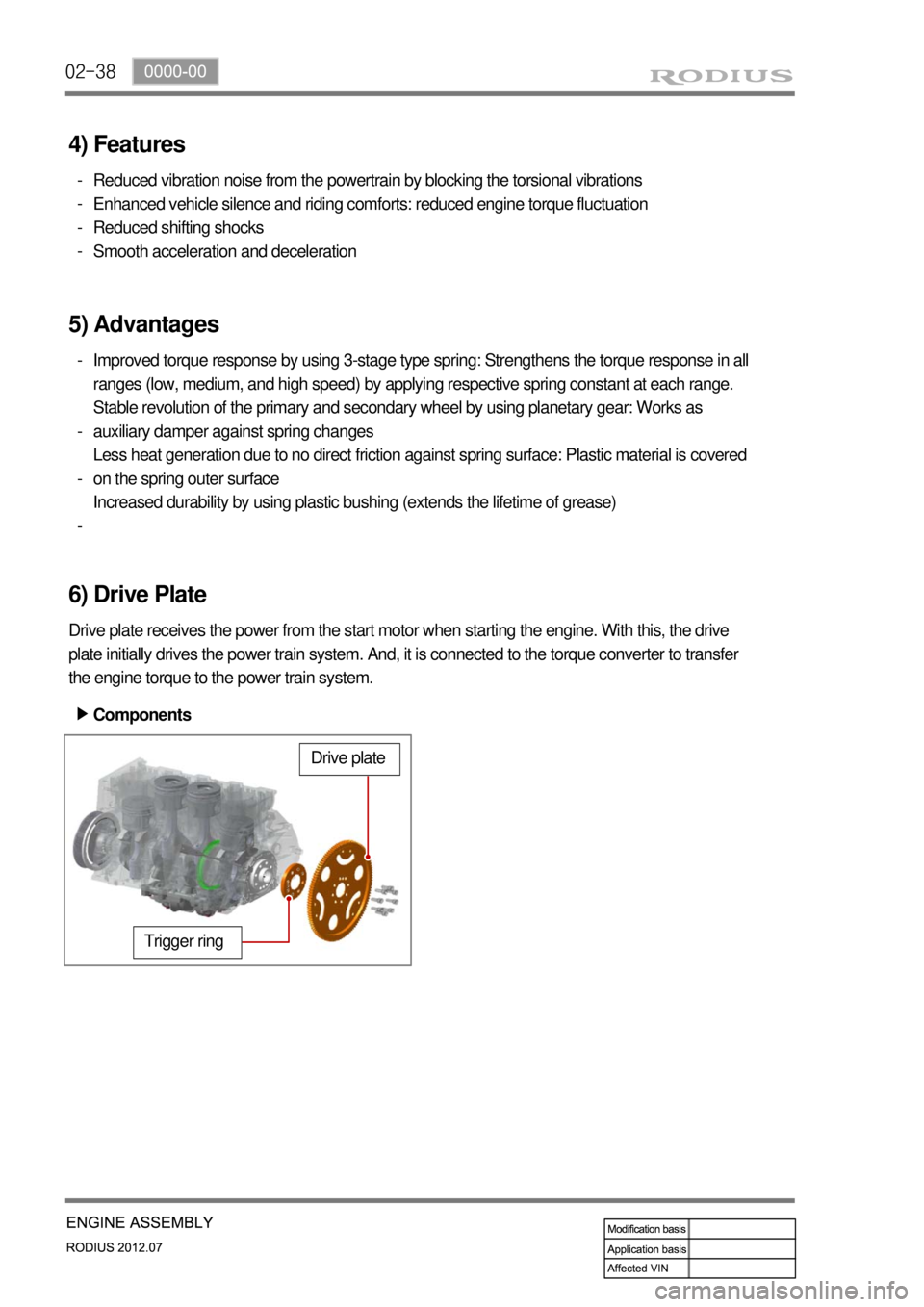
6) Drive Plate
Drive plate receives the power from the start motor when starting the engine. With this, the drive
plate initially drives the power train system. And, it is connected to the torque converter to transfer
the engine torque to the power train system.
Trigger ring
Drive plate
Components ▶
Page 252 of 715

06-111914-01
3. TROUBLESHOOTING
The followings are cautions to take in handling defects of turbocharger, which must be fully aware
of.
1) Cautions
After stopping the engine, check whether the bolts on pipe connecting section are loose as
well as the connecting condition of vacuum port and modulator, which is connected to the
actuator.
During idling of the engine, check for leakage in the connecting section of pipe (hoses and
pipes, duct connections, after the turbocharger) by applying soap water. The leakage condition
in the engine block and turbine housing opening can be determined by the occurrence of
abnormal noise of exhaust.
By running the engine at idle speed, abnormal vibration and noise can be checked.
Immediately stop the engine when abnormal vibration and noise is detected and make
thorough inspection whether the turbocharger shaft wheel has any damages as well as
checking the condition of connections between pipes.
In case where the noise of engine is louder than usual, there is possibility of dampness in the
areas related with air cleaner and engine or engine block and turbocharger. And it could affect
the smooth supply of engine oil and discharge.
Check for damp condition in exhaust gas when there is sign of thermal discoloration or
discharge of carbon in connecting area of the duct.
When the engine rotates or in case where there is change in noise level, check for clogging of
air cleaner or air cleaner duct or if there is any significant amount of dust in the compressor
housing.
During the inspection of center housing, inspect inside of the housing by removing the oil drain
pipe to check for sludge generation and its attachment condition at shaft area or turbine side.
Inspect or replace the air cleaner when the compressor wheel is damaged by inflow of foreign
materials.
Inspect both side of the turbocharger wheel after removing inlet and outlet pipe of the
turbocharger. 1.
2.
3.
4.
5.
6.
7.
8.
9.
Page 564 of 715
03-73010-00
1. OVERVIEW
The hydraulic clutch transmits the force required to operate the clutch pedal to the concentric
slave cylinder fitted to the clutch housing as a hydraulic pressure.
(The hydraulic pressure is transmitted in the following order: Clutch pedal - Clutch master cylinder
- Clutch pipe - Clutch damper - Clutch pipe and hose - Concentric slave cylinder - Pressure
plate - Flywheel.)
If a driver depress the clutch pedal, the hydraulic pressure is generated in the master cylinder. It is
transmitted to the concentric slave cylinder through the pipe, resulting in the cylinder being forced
out. At this time, the clutch disc is forced against the cylinder by pushing the cover. This, in turn,
remove the flywheel from the pressure plate. As a consequence, the power from the engine will be
cut off and the gear change can be carried out.
Page 568 of 715
03-113010-00
3. DUAL MASS FLYWHEEL (DMF)
The dual mass flywheel (DMF) is of having a mass divided into two halves.
While one mass is connected to the engine crankshaft, which is affected by the mass moment of
inertia of the engine, the other mass is affected by one of the transmission.
The divided dual masses are connected to the coil spring and damping system internally.
The DMF has the following benefits: ▶
Reducing fuel consumption by lowering engine speed
Reducing rattling noise and vehicle vibration in all driving ranges
Reducing synchronization wear
Facilitating gear change
Protecting power train parts by preventing excessive load from being delivered -
-
-
-
-
Primary flywheel
Secondary flywheel
Arc damper spring
Torque limiter
Ring gear 1.
2.
3.
4.
5.
Page 573 of 715

05-6
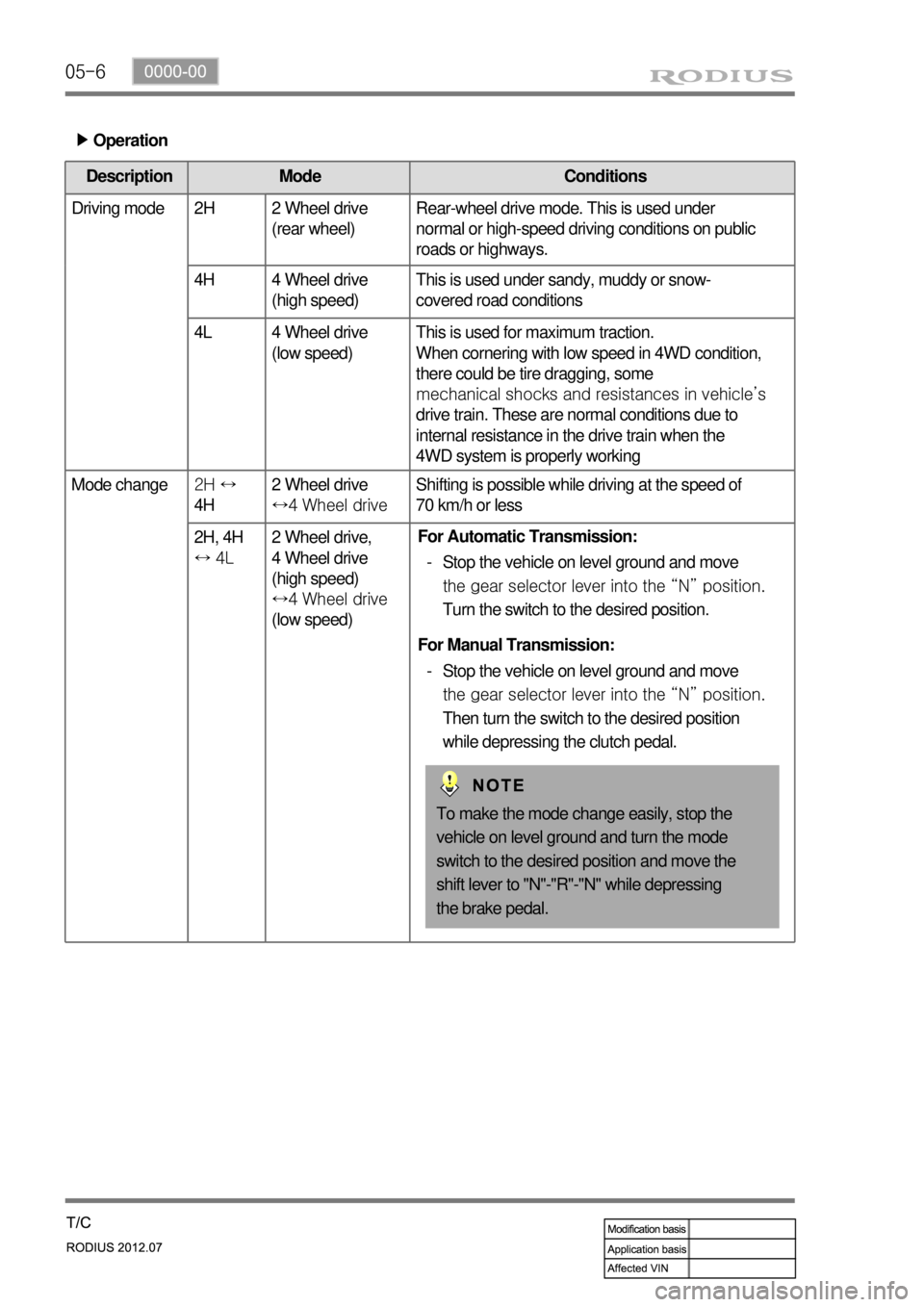
Operation ▶
Description Mode Conditions
Driving mode 2H 2 Wheel drive
(rear wheel)Rear-wheel drive mode. This is used under
normal or high-speed driving conditions on public
roads or highways.
4H 4 Wheel drive
(high speed)This is used under sandy, muddy or snow-
covered road conditions
4L 4 Wheel drive
(low speed)This is used for maximum traction.
When cornering with low speed in 4WD condition,
there could be tire dragging, some
mechanical shocks and resistances in vehicle’s
drive train. These are normal conditions due to
internal resistance in the drive train when the
4WD system is properly working
Mode change2H ↔
4H 2 Wheel drive
↔4 Wheel driveShifting is possible while driving at the speed of
70 km/h or less
2H, 4H
↔ 4L 2 Wheel drive,
4 Wheel drive
(high speed)
↔4 Wheel drive
(low speed)
To make the mode change easily, stop the
vehicle on level ground and turn the mode
switch to the desired position and move the
shift lever to "N"-"R"-"N" while depressing
the brake pedal. For Automatic Transmission:
Stop the vehicle on level ground and move
the gear selector lever into the “N” position.
Turn the switch to the desired position. -
For Manual Transmission:
Stop the vehicle on level ground and move
the gear selector lever into the “N” position.
Then turn the switch to the desired position
while depressing the clutch pedal. -