Page 629 of 715
09-214891-01
▶RISE (ESP is working) Mode
The shuttle valve and inlet valve will be open and the separation valve and outlet valve will be
closed. Then, the pump is operated. When ESP operates while the ABS is operating, the pressure
will be increased continuously until just before the corresponding wheel gets locked.
Page 630 of 715
09-22
2) Electric Circuit Diagram
Wheel speed sensor, Stop lamp switch, Self diagnostic connector, Warning lamp (ABS/ESP) ▶
Page 632 of 715

10-34891-01
1. SYSTEM OVERVIEW
When braking suddenly or braking on slippery roads, the vehicle keeps moving forward but the wheels
are locking and not rotating. If these happen, the vehicle may lose stability or rotate resulting in an
accident. ABS helps to maintain directional stability and control of the vehicle. ABS is designed to secure
more safety and increase the control of steering wheel during emergency braking situation. But, ABS
does not guarantee perfect safety beyond its physical limit. ABS in this vehicle contains EBD function. In
normal driving conditions, the brake system operates without ABS function.
1) Basic Theory of ABS Function
To give you a better understanding of the tasks and functions of ABS, we will first look at the physics
principles.
▶Stopping distance
The stopping distance depends on the vehicle weight and initial speed when braking starts. This also
applies for vehicle with ABS, where ABS always tries to set an optimum brake force on each wheel. As
great forces are exerted between the tires and the carriageway when braking, even with ABS the wheels
may scream and rubber is left on the road. With an ABS skid mark one may be able to clearly recognize
the tire profile. The skid mark of an ABS vehicle does not however leave any hint of the speed of the
vehicle in the case of an accident, as it can only be clearly drawn at the start of braking.
▶Brake force on a wheel
The maximum possible brake force on a wheel depends on the wheel load and the adhesion coefficient
between tire and carriageway. With a low adhesion coefficient the brake force, which can be obtained is
very low. You are bound to know the result already from driving on winter roads. With a high adhesion
coefficient on a dry road, the brake force, which can be obtained, is considerably higher. The brake
force, which can be obtained, can be calculated from below formula:
Page 633 of 715
10-4
2) Maximum Brake Force
FBmax = wheel load FR x coefficient of friction (Mh)
The braking process cannot be described
sufficiently accurately with the brake forces
calculated. The values calculated only apply if
the wheel is not locked. In the case of a locking
wheel, the static friction turns into lower sliding
friction, with the result that the stopping distance
is increased. This loss of friction is termed "slip"
in specialist literature.
Page 634 of 715
10-54891-01
Warning Lamps
EBD warning lamp ABS warning lamp
2. COMPONENTS AND LAYOUT
The basic functions of ABS system are same with previous version. However, the wheel speed sensing
type is different from previous version.
For details about the components, refer to Chapter "ESP".
Front Active Wheel Speed Sensor
4WD 2WD
ABS HECU
Rear Active Wheel
Speed Sensor
Page 636 of 715

10-74891-01
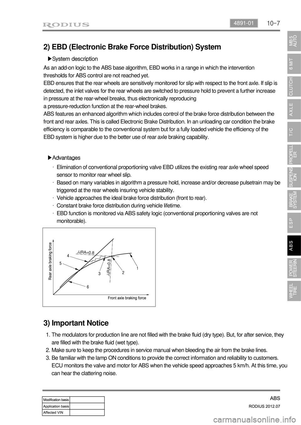
2) EBD (Electronic Brake Force Distribution) System
▶System description
As an add-on logic to the ABS base algorithm, EBD works in a range in which the intervention
thresholds for ABS control are not reached yet.
EBD ensures that the rear wheels are sensitively monitored for slip with respect to the front axle. If slip is
detected, the inlet valves for the rear wheels are switched to pressure hold to prevent a further increase
in pressure at the rear-wheel breaks, thus electronically reproducing
a pressure-reduction function at the rear-wheel brakes.
ABS features an enhanced algorithm which includes control of the brake force distribution between the
front and rear axles. This is called Electronic Brake Distribution. In an unloading car condition the brake
efficiency is comparable to the conventional system but for a fully loaded vehicle the efficiency of the
EBD system is higher due to the better use of rear axle braking capability.
▶Advantages
Elimination of conventional proportioning valve EBD utilizes the existing rear axle wheel speed
sensor to monitor rear wheel slip.
Based on many variables in algorithm a pressure hold, increase and/or decrease pulsetrain may be
triggered at the rear wheels insuring vehicle stability.
Vehicle approaches the ideal brake force distribution (front to rear).
Constant brake force distribution during vehicle lifetime.
EBD function is monitored via ABS safety logic (conventional proportioning valves are not
monitorable). ·
·
·
·
·
3) Important Notice
The modulators for production line are not filled with the brake fluid (dry type). But, for after service, they
are filled with the brake fluid (wet type).
Make sure to keep the procedures in service manual when bleeding the air from the brake lines.
Be familiar with the lamp ON conditions to provide the correct information and reliability to customers.
ECU monitors the valve and motor for ABS when the vehicle speed approaches 5 km/h. At this time, you
can hear the clattering noise. 1.
2.
3.
Page 637 of 715
10-8
4. HYDRAULIC CIRCUIT DIAGRAM
1) Hydraulic Circuit of ABS
The vehicle equipped only with the ABS controls the wheel’s braking force using three 3-channel
4-sensor method. The front wheels that are the primary circuit of the brake system is composed of two
wheel speed sensors and two channel valves system with two inlet valves and two outlet valves. The
rear wheels that are the secondary circuit of the brake system is composed of two wheel speed sensors,
one inlet valve and one outlet valve. This system is similar to the one from the previous model.
Page 638 of 715
10-94891-01
2) ABS Circuit Per ABS Operation Range
▶Hydraulic Pressure Circuit when ABS is Not Operating
The hydraulic pressure in the master cylinder increases through the vacuum booster and it is delivered
to the wheel via the normal open inlet valve. At this moment, the normally-closed outlet valve is closed.
The speed of the wheel that hydraulic pressure is delivered reduces gradually.
▶No Hydraulic Pressure Circuit when ABS is Operating
As hydraulic pressure on each wheel increases, the wheel tends to lock. In order to prevent the wheel
from locking, the hydraulic valve modulator operates the inlet valve control solenoid to close the inlet
valve and stop the hydraulic pressure increases. At this moment, the outlet valve is closed. This
procedure helps the wheel to maintain a stable hydraulic pressure.