Page 363 of 715

15-38
Relay box
A/C
compressorHFM (intake air
temperature)Cooling fan
module
MB 5 A/T (ATF
temperature)Coolant
temperature
sensor
(12) Cooling fan control
A. Overview of cooling fan and A/C compressor
The cooling system maintains the engine temperature at an efficient level during all engine operating
conditions. The water pump draws the coolant from the radiator. The coolant then circulates through
water jackets in the engine block, the intake manifold, and the cylinder head. When the coolant reaches
the operating temperature of the thermostat, the thermostat opens. The coolant then goes back to the
radiator where it cools. The heat from automatic transmission is also cooled down through the radiator
by circulating the oil through the oil pump. ECU controls the electric cooling fans with three cooling fan
relays to improve the engine torque and air conditioning performance.
For detailed information, refer to Chapter "Air Conditioning System".
B. Components
D20DTR ECU
Refrigerant
Page 365 of 715

15-40
D. Cooling fan and A/C compressor control
Conditions for cooling fan control ▶
The PWM cooling fan is set by coolant temperature and A/C refrigerant pressure. And, the setting value
in A/T equipped vehicle may vary according to the internal oil temperature. The The engine ECU
controls the PWM cooling fan unit based on various signals to get the optimized temperature during
engine running.
PWM cooling fan control according to coolant temperature and vehicle speed -
The PWM cooling fan starts running
from 89℃ of coolant temperature
PWM cooling fan control according to transmission fluid temperature (A/T)
1. PWM duty under 129℃: 0%
2. PWM duty over 130℃: 94.4% -
PWM cooling fan control according to A/C refrigerant pressure -
PWM duty value sharply increases
when the A/C refrigerant pressure goes
over 10 bar. And, it slowly decreases
when A/C refrigerant pressure goes
down below 14 bar (A/C compressor
OFF). PWM duty
Refrigerant pressure
(bar)under 101℃: The PWM duty value
decreases when the vehicle speed
increases
over 105℃: The PWM duty value
is fixed at 94.4% -
-
Page 374 of 715

15-490000-00
E. Cautions
Use only specified Engine Oil (approved by MB Sheet 229.51) for CDPF. -
Use only specified engine oil (Low Ash Oil) ▶
The vehicle equipped with CDPF should use specific engine oil to improve the engine performance
and fuel economy, and ensure the service life of CDPF. -
Issue with normal engine oil ▶
Sulfur, one of the contents of engine oil is burned and generates soot that is not regenerated by the
DPF. This remains on the filter as ashes and keeps accumulating. Eventually, this ashes will block
the filter. -
Benefit for specified engine oil ▶
Minimized the sulfur content of engine oil which reduces the service life.
Improved fuel economy and emission level of CO2 with high performance and low viscosity.
Increased service life of engine oil with high resistance to temperature. -
-
-
Problems when using unspecified engine oil ▶
The service life of filter may be reduced by 30% or more by the ashes accumulated on the filter.
The fuel economy may be reduced because of engine rolling resistance, frequent regeneration of
DPF. -
-
These problems are also caused by oil with high sulfur content, such as tax exemption oil and
heating oil, etc. *
Page 403 of 715

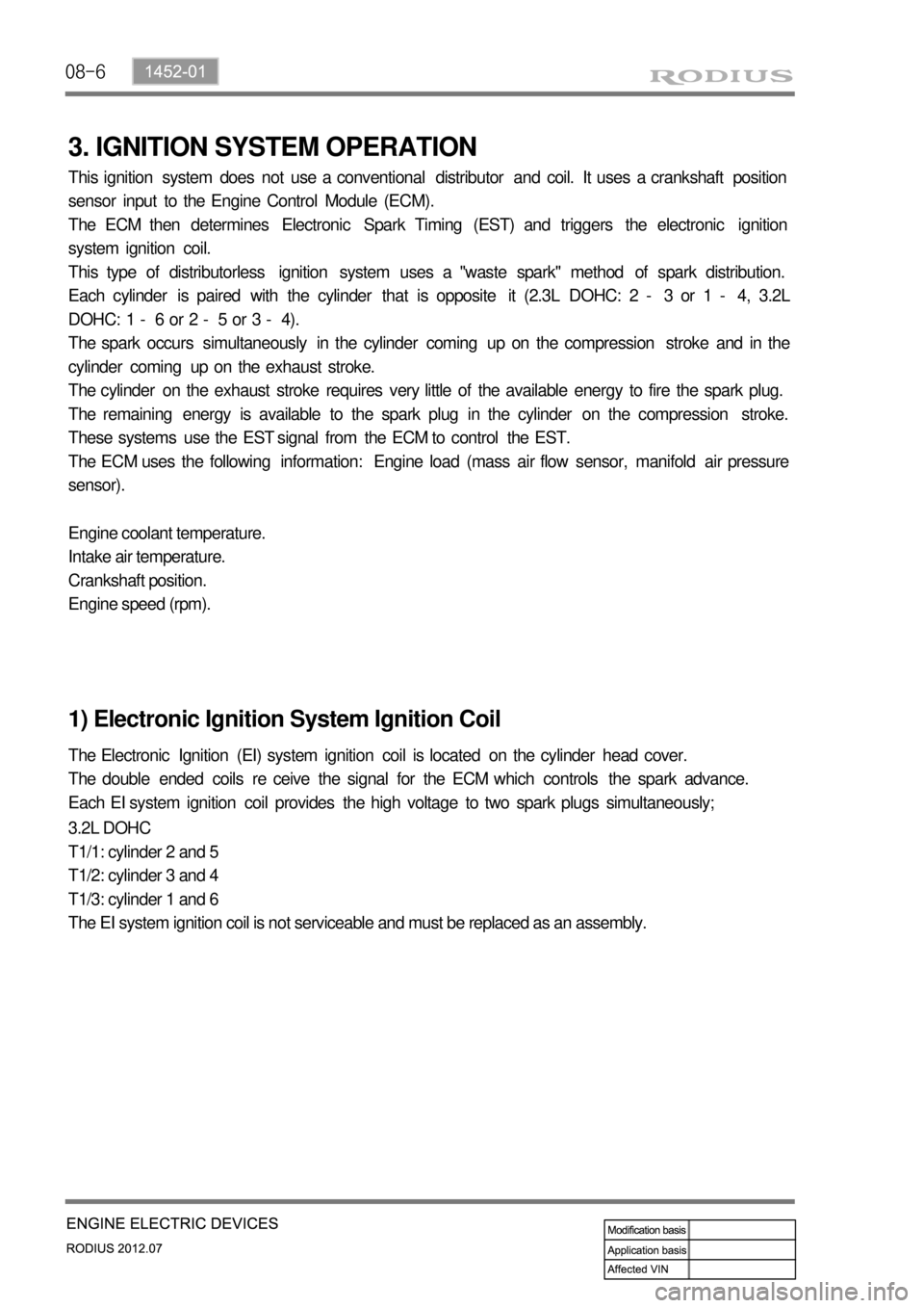
08-6
3. IGNITION SYSTEM OPERATION
This ignition system does not use a conventional distributor and coil. It uses a crankshaft position
sensor input to the Engine Control Module (ECM).
The ECM then determines Electronic Spark Timing (EST) and triggers the electronic ignition
system ignition coil.
This type of distributorless ignition system uses a "waste spark" method of spark distribution.
Each cylinder is paired with the cylinder that is opposite it (2.3L DOHC: 2 - 3 or 1 - 4, 3.2L
DOHC: 1 - 6 or 2 - 5 or 3 - 4).
The spark occurs simultaneously in the cylinder coming up on the compression stroke and in the
cylinder coming up on the exhaust stroke.
The cylinder on the exhaust stroke requires very little of the available energy to fire the spark plug.
The remaining energy is available to the spark plug in the cylinder on the compression stroke.
These systems use the EST signal from the ECM to control the EST.
The ECM uses the following information: Engine load (mass air flow sensor, manifold air pressure
sensor).
Engine coolant temperature.
Intake air temperature.
Crankshaft position.
Engine speed (rpm).
1) Electronic Ignition System Ignition Coil
The Electronic Ignition (EI) system ignition coil is located on the cylinder head cover.
The double ended coils re ceive the signal for the ECM which controls the spark advance.
Each EI system ignition coil provides the high voltage to two spark plugs simultaneously;
3.2L DOHC
T1/1: cylinder 2 and 5
T1/2: cylinder 3 and 4
T1/3: cylinder 1 and 6
The EI system ignition coil is not serviceable and must be replaced as an assembly.
Page 522 of 715
01-33650-01
Diameter( Torque converter) 270mm
Lockup function Yes
Gear ratios 1st 3.595
2nd 2.186
3rd 1.405
4th 1.000
5th 0.831
Reverse:
S mode / W mode3.167/1.926
Driving type 2WD(4WD)
Fluid specification Shell ATF 134
Fluid capacityapprox. 8ℓ
Selected lever
indicationP.R.N.D Mechanical
D+/D- Electrical
Parking lock systemBrake switch(signal) → TGS lever
Reverse lock systemCAN → TGS lever
Selected lever
indicationP.R.N.D Lever position
1, 2, 3, 4, 5 CAN
Oil temperature
sensorResistance: R, D0.5 ~ 2.5kΩ
Resistance: P, N20kΩ
TCU EGS 52
Shift solenoid
valve(25℃)Resistance3.8 ± 0.2Ω
Operating distance 0.2mm
Operating current 1.5 ~ 2A
Item W5A580(2WD) / W5A400(4WD)
Input torque 450Nm
1. SPECIFICATIONS
Page 540 of 715
01-213650-01
▶Solenoid, Oil temperature sensor, Speed sensor (N2, N3)
Page 641 of 715
11-34610-00
1. SPECIFICATIONS
Description Specification
Steering wheelType 4-spoke type
Outer diameter (mm) 390
Steering gear boxType Rack and pinion type
Steering angleInner36.4°
Outer31.5°
Steering oil pumpType Vane type
Maximum pressure (kgf/cm2)90±3
Pulley size (mm)Ø115
Operating temperature-40℃ ~ 150℃
Steering oilType S-PSF3
Capacity (L) approx. 1.1
Minimum turning radius (m) 6.08
Tilting angle±3°
Page 646 of 715

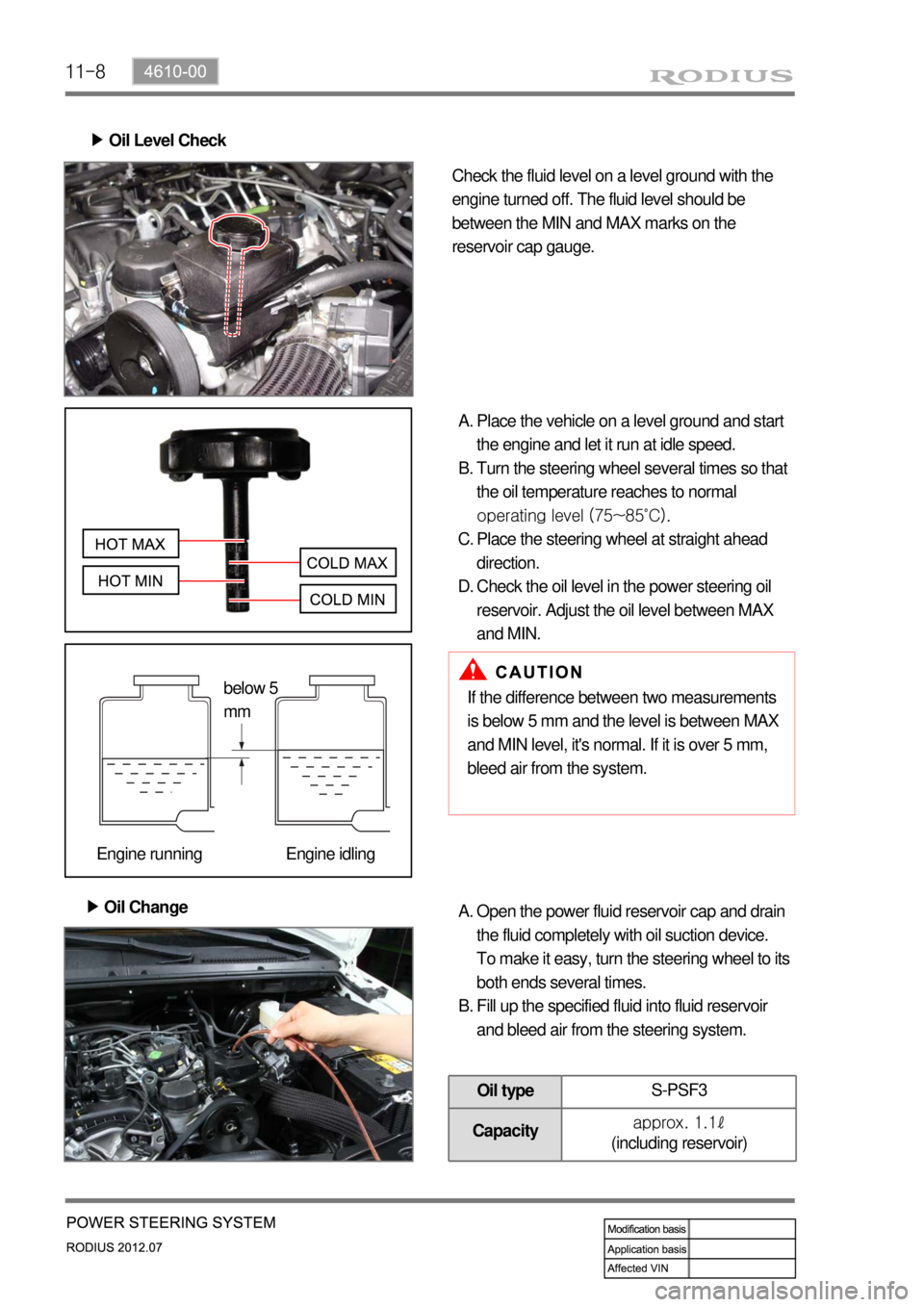
11-8
Oil Level Check ▶
Check the fluid level on a level ground with the
engine turned off. The fluid level should be
between the MIN and MAX marks on the
reservoir cap gauge.
Place the vehicle on a level ground and start
the engine and let it run at idle speed.
Turn the steering wheel several times so that
the oil temperature reaches to normal
operating level (75~85˚C).
Place the steering wheel at straight ahead
direction.
Check the oil level in the power steering oil
reservoir. Adjust the oil level between MAX
and MIN. A.
B.
C.
D.
Oil Change ▶
If the difference between two measurements
is below 5 mm and the level is between MAX
and MIN level, it's normal. If it is over 5 mm,
bleed air from the system.
Open the power fluid reservoir cap and drain
the fluid completely with oil suction device.
To make it easy, turn the steering wheel to its
both ends several times.
Fill up the specified fluid into fluid reservoir
and bleed air from the steering system. A.
B.
Oil typeS-PSF3
Capacityapprox. 1.1ℓ
(including reservoir)
below 5
mm
Engine running Engine idling