Page 427 of 600

2412-02
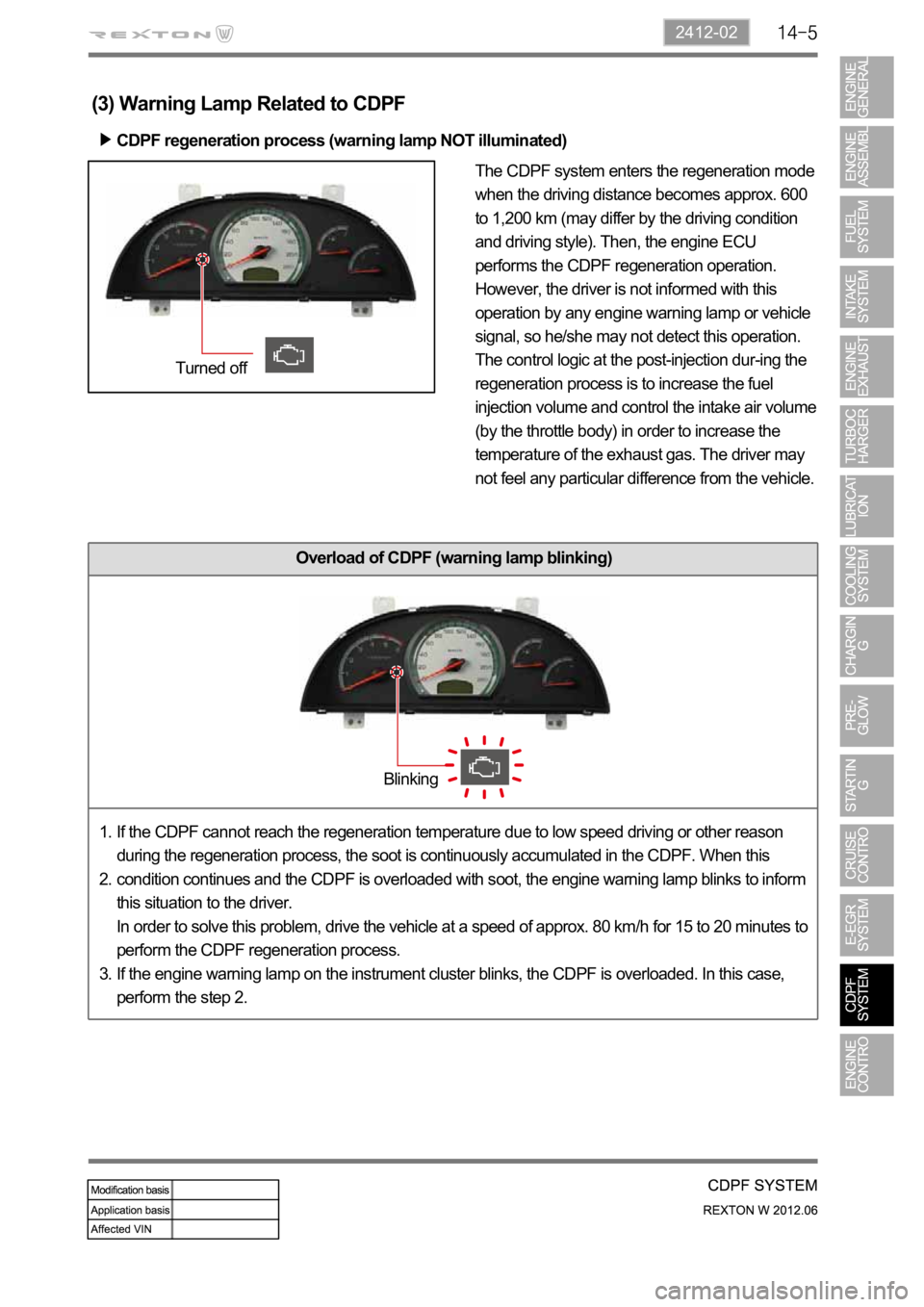
The CDPF system enters the regeneration mode
when the driving distance becomes approx. 600
to 1,200 km (may differ by the driving condition
and driving style). Then, the engine ECU
performs the CDPF regeneration operation.
However, the driver is not informed with this
operation by any engine warning lamp or vehicle
signal, so he/she may not detect this operation.
The control logic at the post-injection dur-ing the
regeneration process is to increase the fuel
injection volume and control the intake air volume
(by the throttle body) in order to increase the
temperature of the exhaust gas. The driver may
not feel any particular difference from the vehicle.
Overload of CDPF (warning lamp blinking)
(3) Warning Lamp Related to CDPF
CDPF regeneration process (warning lamp NOT illuminated)
If the CDPF cannot reach the regeneration temperature due to low speed driving or other reason
during the regeneration process, the soot is continuously accumulated in the CDPF. When this
condition continues and the CDPF is overloaded with soot, the engine warning lamp blinks to inform
this situation to the driver.
In order to solve this problem, drive the vehicle at a speed of approx. 80 km/h for 15 to 20 minutes to
perform the CDPF regeneration process.
If the engine warning lamp on the instrument cluster blinks, the CDPF is overloaded. In this case,
perform the step 2. 1.
2.
3.
Turned off
Blinking
Page 445 of 600
0000-00
Fuel rail pressure
sensor
(2) Components for ECU Input
CAN
- ABS & ESP
- GCU
- Instrument
cluster
- TCU
- STICSSwirl valve
position sensor
Differential
pressure sensorE-EGR valve
position sensorCamshaft position
sensorCoolant
temperature
sensor
Exhaust gas
temperature
sensorHFM sensorOxygen sensorT-MAP sensor
Crankshaft
position sensorAccelerator pedal
sensorThrottle position
sensorKnock sensor
-Auto cruise switch
- Rear right wheel
speed (without ABS)
- Refrigerant pressure
sensor
- Clutch pedal signal
- Blower switch signal
- Brake pedal signal
Water sensor
Page 446 of 600
(3) Components for ECU Output
CAN
E-EGR cooler
bypass valve
- Instrument cluster
- TCU
- Self diagnosis
PTC heaterCooling fan
E-EGR valve
Variable swirl
valveE-VGT actuatorIMV valve
A/C compressorInjectorThrottle position
sensor
- Glow plug unit
- ABS & ESP unit
- GCU
Page 482 of 600
(14) Immobilizer control
A. Overview
The Immobilizer System provides an additional theft deterrent to the vehicle in which it is installed and
prevents it from being started by unauthorized persons. The transponder integrated in the key and the
engine control unit have the same code. When the ignition key with the integrated transponder is turned
to the ON position, the ECU (Engine Control Unit) checks the crypto code of the key and, if correct,
allows the vehicle to start the engine.
For details, refer to Chapter "Immobilizer".
B. Components
Basic components (ignition key system)
D20DTR ECUImmobilizer antennaInstrument cluster
Immobilizer keyStart motor
Page 552 of 600

1725-12
If the CDPF cannot reach the regeneration
temperature due to low speed driving or other
reason during the regeneration process, the soot
is continuously accumulated in the CDPF. When
this condition continues and the CDPF is
overloaded with soot, the engine warning lamp
blinks to inform this situation to the driver.
In order to solve this problem, drive the vehicle at
a speed of approx. 80 km/h for 15 to 20 minutes
to perform the CDPF regeneration process.
If the engine warning lamp on the instrument
cluster blinks, the CDPF is overloaded. In this
case, perform the step 2. 1.
2.
3.
If the vehicle is driven at a speed of 5 to 10 km/h
for an extended period of time, the soot
accumulated in the CDPF cannot be burnt as the
CDPF cannot reach the regeneration temperature.
Then, an excessive amount of soot can be
accumulated in the CDPF.
This case is much worse than the simple overload
of the CDPF. To inform this to the driver, the
engine warning lamp comes on and the engine
power is decreased to protect the system.
To solve this problem, blow soot between the
engine and exhaust system several times and
erase the related DTC. Then, check if the same
DTC is regenerated again. If so, check the DTC
related to the differential pressure sensor. 1.
2.
3.
Actually, the DTC for the CDPF is generated more often by the component related to the CDP
F
system, such as the differential pressure sensor, than by excessive soot in the CDPF.
Illuminating
Blinking