Page 271 of 600
2. TIGHTENING TORQUE
Component SizeBolt
QuantitySpecified torque
(Nm)Remark
(Total torque)
Main bearing cap
10 Not re-usable
Connecting rod cap
850 to 80 Nm
Rear cover
6-
Oil pump
3-
Flywheel
860 to 100 Nm
Crankshaft center bolt
1660 to 720 Nm
Not re-usable
Oil pan
18-
2-
2-
2-
2-
HP pump main nut
1-
HP pump bolt
3-
Cylinder head
12 85Nm-
Camshaft cap
16-
4-
Exhaust stud bolt 10
-
Exhaust sprocket bolt
1-
Chain tensioner screw
bolt
1-
Coolant temperature
sensor1
-
Auto tensioner
1-
1-
Coolant pump
1-
Page 340 of 600

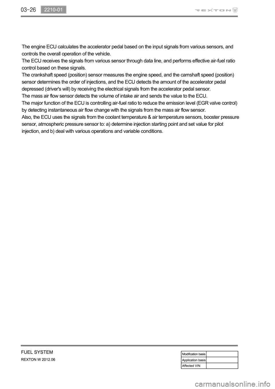
The engine ECU calculates the accelerator pedal based on the input signals from various sensors, and
controls the overall operation of the vehicle.
The ECU receives the signals from various sensor through data line, and performs effective air-fuel ratio
control based on these signals.
The crankshaft speed (position) sensor measures the engine speed, and the camshaft speed (position)
sensor determines the order of injections, and the ECU detects the amount of the accelerator pedal
depressed (driver's will) by receiving the electrical signals from the accelerator pedal sensor.
The mass air flow sensor detects the volume of intake air and sends the value to the ECU.
The major function of the ECU is controlling air-fuel ratio to reduce the emission level (EGR valve control)
by detecting instantaneous air flow change with the signals from the mass air flow sensor.
Also, the ECU uses the signals from the coolant temperature & air temperature sensors, booster pressure
sensor, atmospheric pressure sensor to: a) determine injection starting point and set value for pilot
injection, and b) deal with various operations and variable conditions.
Page 370 of 600
1914-01
E-VGT turbocharger
Improves engine power
2. COMPONENTS
Engine ECU (D20DTR)
E-VGT duty controlAccelerator pedal position
sensor
Transfers driver's will to
accelerate to ECU
Atmospheric pressure, RPM
signal
HFM sensor
Improves the engine powerCoolant temperature sensor
Operates the VGT according to
engine warm-upT-MAP sensor
Booster pressure and
temperature
Page 378 of 600
1520-00
1. SPECIFICATION
Unit Description Specification
Cooling system Type Water cooling, forced circulation
Coolant Capacity approx. 8.5 L
Radiator Core size 662.1W x 510H x 27T
Flow type Cross flow
Min. cooling capacity over 72,000 kcal/h
Antifreeze Type Long life coolant
Mixing ratio
(water:antifreeze)50 : 50
Cooling fan module Type Electric
Capacity
Control type PWM type
Coolant reservoir Capacity over 1.5 L
Circulation Closed roof type
Pressure cap Screw type, 1.4bar
Vacuum valve Screw type, 1.4bar
Thermostat Type Wax pallet type
Opening temperature
Fully open temperature
Valve lift 8 mm
Page 379 of 600

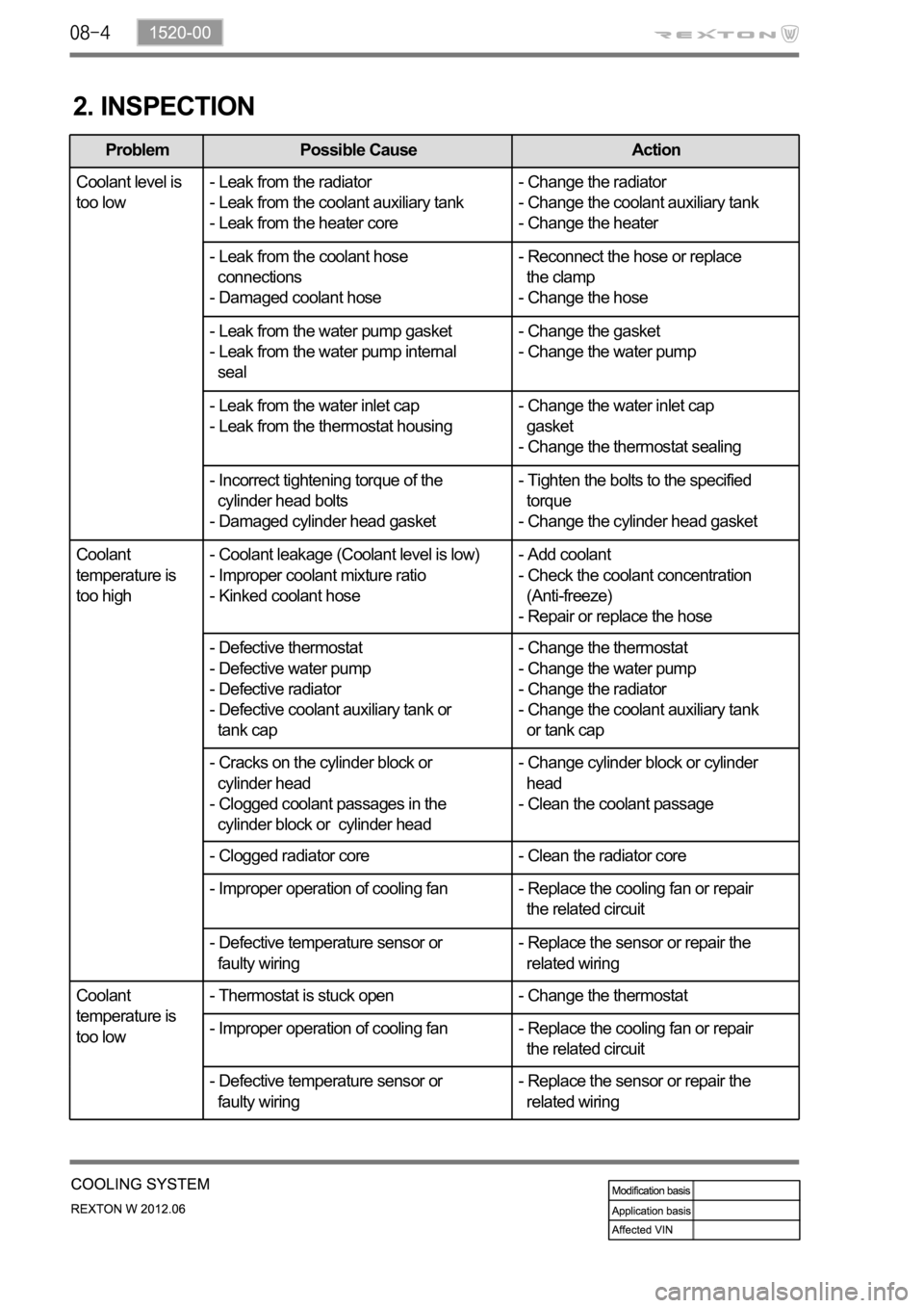
2. INSPECTION
Problem Possible Cause Action
Coolant level is
too low- Leak from the radiator
- Leak from the coolant auxiliary tank
- Leak from the heater core- Change the radiator
- Change the coolant auxiliary tank
- Change the heater
- Leak from the coolant hose
connections
- Damaged coolant hose- Reconnect the hose or replace
the clamp
- Change the hose
- Leak from the water pump gasket
- Leak from the water pump internal
seal- Change the gasket
- Change the water pump
- Leak from the water inlet cap
- Leak from the thermostat housing- Change the water inlet cap
gasket
- Change the thermostat sealing
- Incorrect tightening torque of the
cylinder head bolts
- Damaged cylinder head gasket- Tighten the bolts to the specified
torque
- Change the cylinder head gasket
Coolant
temperature is
too high- Coolant leakage (Coolant level is low)
- Improper coolant mixture ratio
- Kinked coolant hose- Add coolant
- Check the coolant concentration
(Anti-freeze)
- Repair or replace the hose
- Defective thermostat
- Defective water pump
- Defective radiator
- Defective coolant auxiliary tank or
tank cap- Change the thermostat
- Change the water pump
- Change the radiator
- Change the coolant auxiliary tank
or tank cap
- Cracks on the cylinder block or
cylinder head
- Clogged coolant passages in the
cylinder block or cylinder head- Change cylinder block or cylinder
head
- Clean the coolant passage
- Clogged radiator core - Clean the radiator core
- Improper operation of cooling fan - Replace the cooling fan or repair
the related circuit
- Defective temperature sensor or
faulty wiring- Replace the sensor or repair the
related wiring
Coolant
temperature is
too low- Thermostat is stuck open - Change the thermostat
- Improper operation of cooling fan - Replace the cooling fan or repair
the related circuit
- Defective temperature sensor or
faulty wiring- Replace the sensor or repair the
related wiring
Page 381 of 600
2) Leak Test
Release the pressure in the system by
loosening the pressure cap of the coolant
reservoir slightly. Then, remove the pressure
cap completely. 1.
Never open the cap until the coolant
prevent any burn.
Add the coolant so that the coolant level is
between MAX and MIN mark on the coolant
auxiliary tank.
Connect the tester to the tank filler and apply
pressure (1.4 bar).
Check all the coolant hoses, pipes and
connections for leaks when the pressure of
the tester drops, and replace or tighten, if
necessary. 2.
3.
4.
3) Thermostat
Immerse the thermostat into the water. Heat the
water and check the valve opening temperature.
Valve opening
temperature
Page 383 of 600
Water pump
The water pump is driven by the engine drive belt and supplies
the coolant to each area of the engine.
Coolant reservoir
Long life coolant is used.
Thermostat
When the engine coolant
starts to open (fully open at
flow to the radiator to maintain
the engine temperature.
1. SYSTEM DESCRIPTION
1) Overview
Water pump
Impeller vane Sealing
Oil filter module
Page 384 of 600
1520-00
Electric fan
Circulates the fresh air forcibly to exchange heat
with the radiator core fin.
Radiator
Releases heat through fins and cools down the hot
coolant as the coolant passes through the tube of the
radiator core.
Coolant temperature sensor
Measures the coolant
temperature and sends the
result to the engine ECU.