Page 502 of 828
04-118210-01
2) Speedometer Gauge
The speedometer indicates the vehicle speed by calculating the signals from the rear left and rear
right wheel speed sensors through ABS or ESP unit. (For the vehicle without ABS or ESP, the
signals are received from the EMS)
If the speedometer gauge vibrates, stops at a certain range or makes an abnormal noise, there
could be defectives in speedometer. However, these symptoms also could be occured when th
e
tire has uneven wear, different tire inflation pressures or different tire specifications.
Perform the speedometer test regarding the tolerance as described. However, it is not similar
simple work in field due to lack of measuring conditions such as test equipment and preciseness.
Check the allowable tolerance of the speedometer and operations of the trip odometer by
using a tester.
Check if the speedometer pointer is shaking and the abnormal noise sounds.
Eliminate the hysteresis by tapping the speedometer. 1.
2.
3.
Page 544 of 828
10-4
Remote contro switches
on steering wheel
USB & AUX module
Front door speakerHandsfree microphone
1. LAYOUT
Page 548 of 828

01-4
This indicator shows the current position of
the gear.
In normal mode: P, R, N, D
Gear indication in “M” mode: 1, 2, 3, 4, 5, 6
Driving gear can be adjusted by operating
the tip switch after moving the gear select
lever in “M” position.
Shift down Shift up
Tip switch on steering wheel ▶
Gear position display on instrument cluste▶
Gear select lever ▶
Mode Switch
W :
S :
Selection of Manual/
Automatic Shift Function
D :
M :Shift Lock Release Button Hole
when Locked in the "P" Position
If you cannot move the gear
select lever from the "P" position,
try to move the lever while
pushing down here with a sharp
object such as a ballpoint pen.
For your safety, turn off the
engine and depress the brake
pedal before the attempt. Tip Switch in “M” Position (Manual Gear Shift)
The shiftable gear can be adjusted by moving this switch to forward and rearward when the
gear select lever is in “M” position.
Positions of gear
select lever
P : Parking
R : Reverse
N : Neutral
D : Drive
Winter mode
Standard mode (Use the
standard mode in normal
driving conditions.)
Automatic shift according to
the driving condition
Manual shift
Page 555 of 828

01-113680-01
1. OVERVIEW
The six speed automatic (M78) transmission
is available in two variants: four wheel drive
and two wheel drive.
The transmission has the following features:
Six Forward Speeds
One reverse gear
A torque converter with an integral converter lock-up clutch
Electronic shift and pressure controls
A single planetary gear-set
A double planetary gear-set
Two hydraulically controlled brake bands
Three multi-plate clutches
All hydraulic functions are directed by electronic solenoids to control: -
-
-
-
-
-
-
-
-
Engagement feel
Shift feel
Shift scheduling
Modulated torque converter clutch applications ·
·
·
·
The transmission contains fully synthetic automatic transmission fluid (ATF) and is filled for life;
therefore it does not require periodic servicing.
Engine power reaches the transmission via a torque converter with integral converter lock-up
clutch.
The six forward gears and one reverse gear are obtained from a single planetary set, followed by
a double planetary set. This type of gear-set arrangement is commonly known as Lepelletier type
gear-set.
The automatic transmission is electronically controlled. The control system is comprised of the
following elements:
External transmission control unit (TCU)
Internal embedded memory module (EMM)
Input and output speed sensors
Valve body unit comprised of four on/off solenoid valves and six variable bleed solenoids
Torque converter -
-
-
-
-
Page 566 of 828

01-22
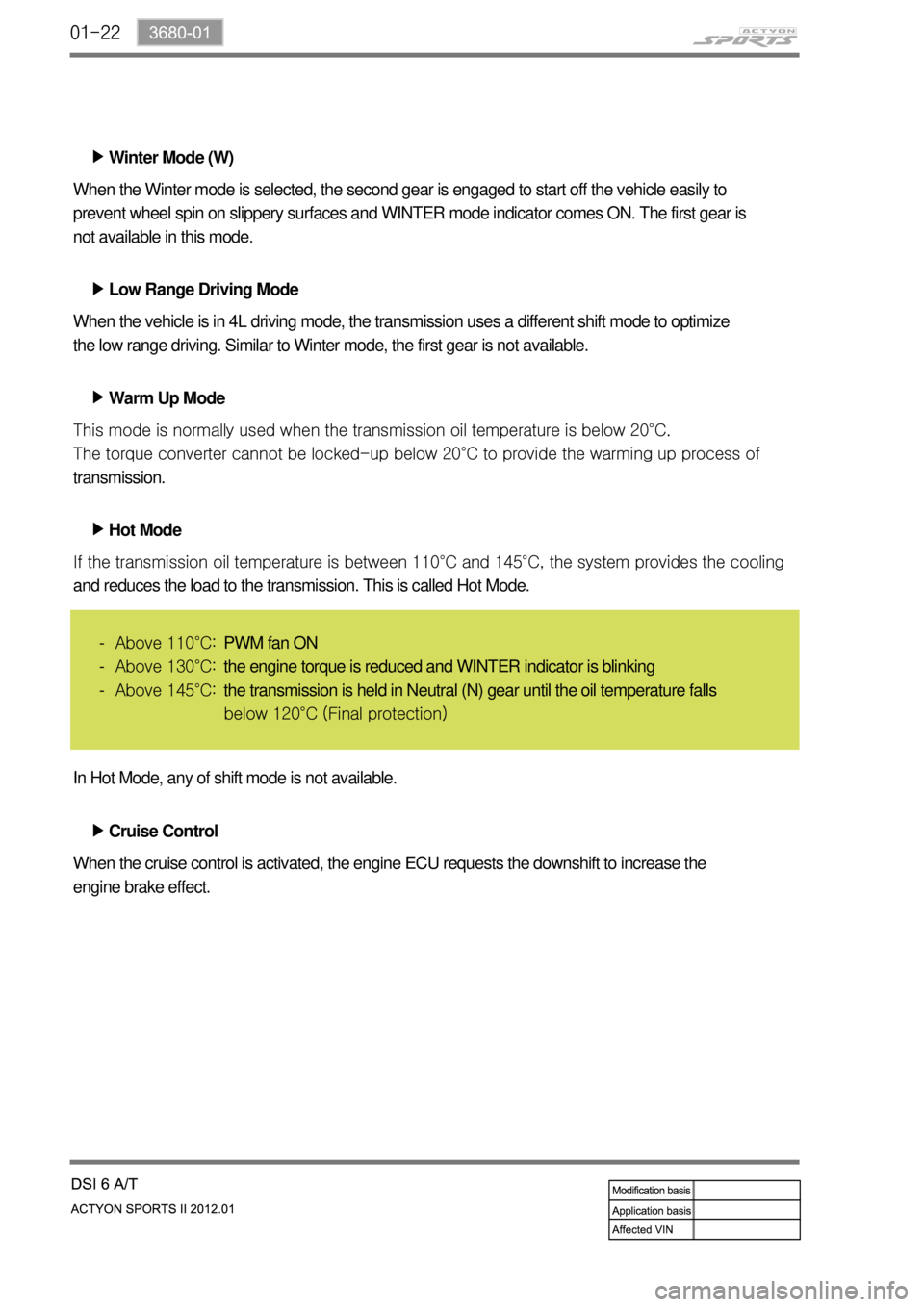
Winter Mode (W) ▶
Low Range Driving Mode ▶
Warm Up Mode ▶ When the Winter mode is selected, the second gear is engaged to start off the vehicle easily to
prevent wheel spin on slippery surfaces and WINTER mode indicator comes ON. The first gear is
not available in this mode.
When the vehicle is in 4L driving mode, the transmission uses a different shift mode to optimize
the low range driving. Similar to Winter mode, the first gear is not available.
This mode is normally used when the transmission oil temperature is below 20°C.
<007b008f008c0047009b009600990098009c008c0047008a00960095009d008c0099009b008c00990047008a0088009500950096009b00470089008c004700930096008a0092008c008b0054009c009700470089008c00930096009e00470059005700b600
6a0047009b00960047009700990096009d0090008b008c0047>the warming up process of
transmission.
Hot Mode ▶
<0070008d0047009b008f008c0047009b009900880095009a00940090009a009a00900096009500470096009000930047009b008c00940097008c00990088009b009c0099008c00470090009a00470089008c009b009e008c008c0095004700580058005700
b6006a004700880095008b00470058005b005c00b6006a0053> the system provides the cooling
and reduces the load to the transmission. This is called Hot Mode.
Above 110°C:
Above 130°C:
Above 145°C: -
-
-
In Hot Mode, any of shift mode is not available.
Cruise Control ▶
When the cruise control is activated, the engine ECU requests the downshift to increase the
engine brake effect.PWM fan ON
the engine torque is reduced and WINTER indicator is blinking
the transmission is held in Neutral (N) gear until the oil temperature falls
below 120°C (Final protection)
Page 619 of 828
04-4
1. OVERVIEW
The hydraulic clutch transmits the force required to operate the clutch pedal to the concentric
slave cylinder fitted to the clutch housing as a hydraulic pressure.
(The hydraulic pressure is transmitted in the following order: Clutch pedal - Clutch master
cylinder - Clutch pipe - Clutch damper - Clutch pipe and hose - Concentric slave cylinder -
Pressure plate - Flywheel.)
If a driver depress the clutch pedal, the hydraulic pressure is generated in the master cylinder. It
is transmitted to the concentric slave cylinder through the pipe, resulting in the cylinder being
forced out. At this time, the clutch disc is forced against the cylinder by pushing the cover. This,
in turn, remove the flywheel from the pressure plate. As a consequence, the power from the
engine will be cut off and the gear change can be carried out.
Page 621 of 828

04-6
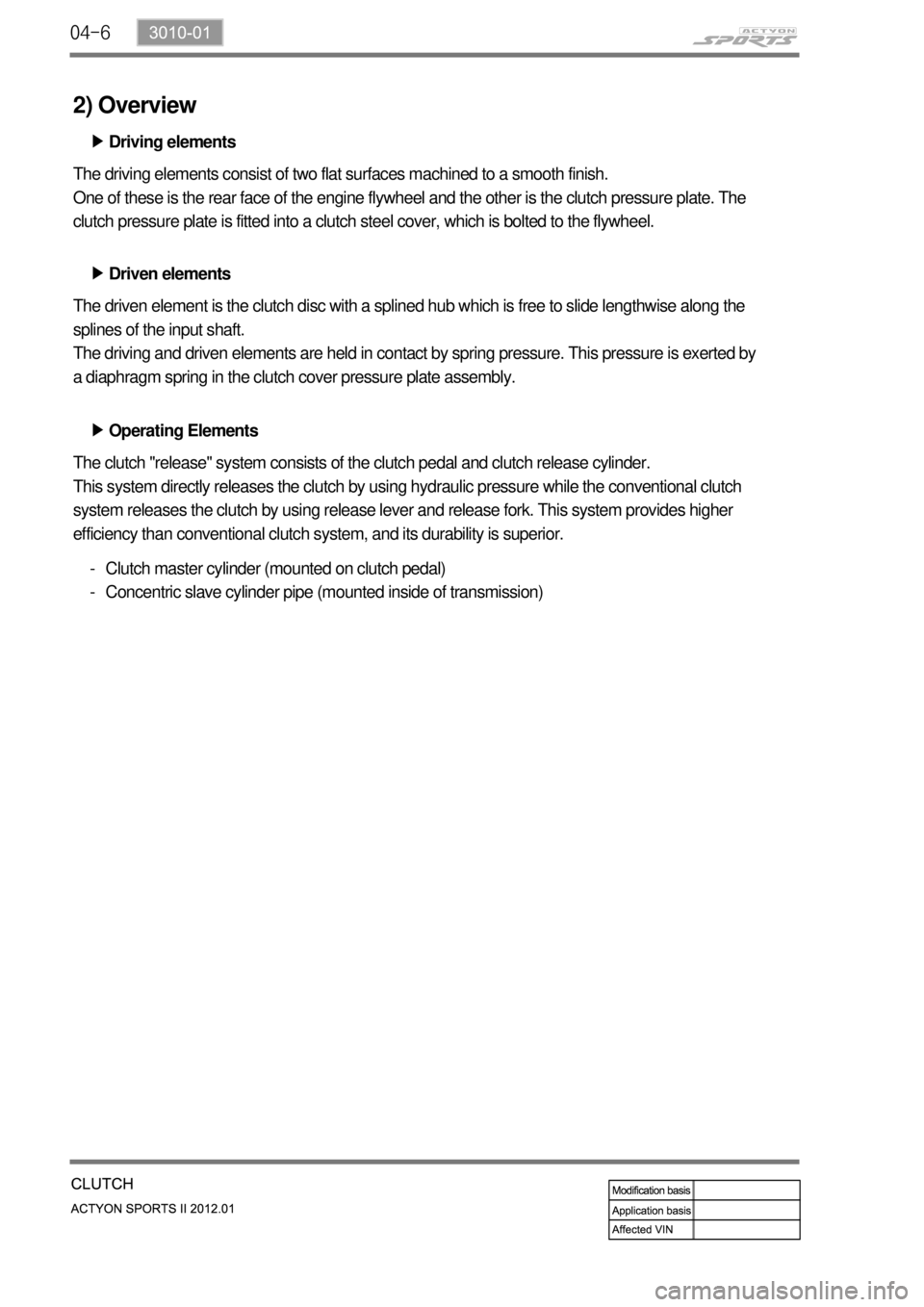
2) Overview
Driving elements ▶
The driving elements consist of two flat surfaces machined to a smooth finish.
One of these is the rear face of the engine flywheel and the other is the clutch pressure plate. The
clutch pressure plate is fitted into a clutch steel cover, which is bolted to the flywheel.
Driven elements ▶
The driven element is the clutch disc with a splined hub which is free to slide lengthwise along the
splines of the input shaft.
The driving and driven elements are held in contact by spring pressure. This pressure is exerted by
a diaphragm spring in the clutch cover pressure plate assembly.
Operating Elements ▶
The clutch "release" system consists of the clutch pedal and clutch release cylinder.
This system directly releases the clutch by using hydraulic pressure while the conventional clutch
system releases the clutch by using release lever and release fork. This system provides higher
efficiency than conventional clutch system, and its durability is superior.
Clutch master cylinder (mounted on clutch pedal)
Concentric slave cylinder pipe (mounted inside of transmission) -
-
Page 622 of 828
04-73010-01
3) Layout
Clutch discClutch cover assembly
Dual mass flywheel (DMF)Concentric slave cylinder
Centering pin