Page 244 of 828

07-4
2. MAINTENANCE
1) Level Check
Park the vehicle on a level ground and apply the parking brake. Stop the engine and wait more
than 5 minutes.
Pull out the dipstick and wipe it with a clean cloth. Reinsert it all the way.
Pull out it again and check the oil level.
The oil level should be between the maximum (Max) mark and minimum (Min) mark on the oil
dipstick. Oil should be replenished before the level goes below the minimum mark. -
-
-
Operating vehicle with insufficient amount of oil can damage the engine. Make sure the engine
oil level is correct and add oil if necessary.
2) Replenishment
If the level gets to the lower point, open the filler cap on top of the cylinder block and add the
genuine oil without exceeding the level of the upper mark.
Recheck the oil level after 5 minutes.
Regularly check the engine oil level and add Ssangyong genuine engine oil if necessary.
Clean the dipstick with clean cloth so that any foreign materials cannot get into the engine.
The oil should not go above the upper mark on the dipstick.
The engine oil may be consumed more if the engine is new. -
-
-
-
Engine oil dipstick
Engine oil filler
Page 248 of 828
08-51520-00
1) Coolant Level Check
Park the vehicle on level ground and apply the parking brake. Stop the engine and wait until it is
cooled down.
The coolant level should be between the MAX and MIN mark on the coolant reservoir.
Check the coolant level. If the level is below the “MIN” mark, immediately add coolant. 1.
2.
Scalding hot coolant and steam could be blown out under pressure, which could cause
serious injury. Never remove the coolant reservoir cap when the engine and radiator are hot.
Avoid any direct contact of the coolant to the painted body of the vehicle. -
-
MAX
MIN
Page 255 of 828

09-51451-01
2) Troubleshooting for Alternator
Item Cause Action
Overcharged
batteryDefective alternator voltage regulator
Replace the alternator
Defective voltage detection wiring Repair or replace
Loose alternator drive belt Adjust the belt tension or replace
Discharged batteryPoor connection of related circuit or
open circuitRetighten the loose connection or
repair open circuit
Defective alternator voltage regulator
Replace the alternator
Defective alternator voltage regulator
Replace the alternator
Terminated battery Replace the battery
Defective ground Repair
Charge warning
lamp does not
come on when
turning on ignition
switch with engine
stoppedDefective alternator voltage regulator
Replace the alternator
Open circuit in charge warning lamp,
fuse or wiringReplace or repair the charge
warning lamp or fuse
Defective ignition switch Replace the ignition switch
Defective ground of alternator circuit Repair
Charge warning
lamp is not turned
off after starting
engineDefective alternator voltage regulator
Replace the alternator
Corroded or worn battery cableRepair or replace the battery cable
Loose alternator drive belReplace the batteryAdjust the belt
tension or replace the belt
Defective wiring harness Repair or replace
Page 271 of 828
11-4
2. TROUBLESHOOTING
ProblemPossible Cause Action
Engine will not
crankLow battery voltage Charge or replace
Loose, corroded or damaged battery cable
Repair or replace
Faulty starter or open circuit
Faulty ignition switch or blown fuse Repair or replace
Poor engine ground Repair
Engine cranks too
slowLow battery voltage Charge or replace
Loose, corroded or damaged battery cable
Repair or replace
Faulty starter
Starter does not
stopFaulty starter
Faulty ignition switch Replace
Engine cranks
normally, but does
not startBroken pinion gear or faulty starter
Replace the starter
Broken flywheel ring gear Replace
Open circuit Repair
Page 324 of 828
15-210000-00
(7) Knocking Control
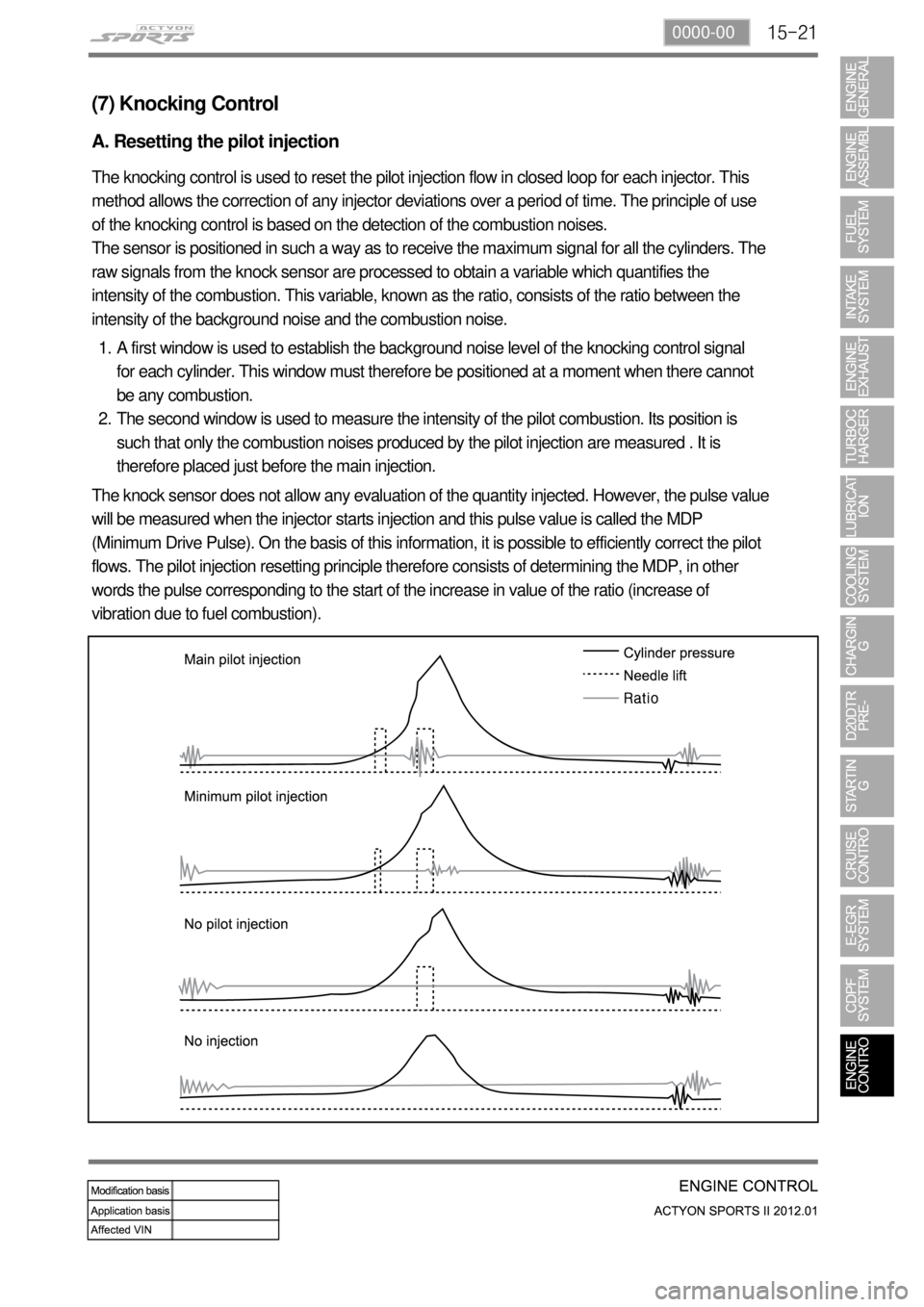
A. Resetting the pilot injection
The knocking control is used to reset the pilot injection flow in closed loop for each injector. This
method allows the correction of any injector deviations over a period of time. The principle of use
of the knocking control is based on the detection of the combustion noises.
The sensor is positioned in such a way as to receive the maximum signal for all the cylinders. The
raw signals from the knock sensor are processed to obtain a variable which quantifies the
intensity of the combustion. This variable, known as the ratio, consists of the ratio between the
intensity of the background noise and the combustion noise.
A first window is used to establish the background noise level of the knocking control signal
for each cylinder. This window must therefore be positioned at a moment when there cannot
be any combustion.
The second window is used to measure the intensity of the pilot combustion. Its position is
such that only the combustion noises produced by the pilot injection are measured . It is
therefore placed just before the main injection. 1.
2.
The knock sensor does not allow any evaluation of the quantity injected. However, the pulse value
will be measured when the injector starts injection and this pulse value is called the MDP
(Minimum Drive Pulse). On the basis of this information, it is possible to efficiently correct the pilot
flows. The pilot injection resetting principle therefore consists of determining the MDP, in other
words the pulse corresponding to the start of the increase in value of the ratio (increase of
vibration due to fuel combustion).
Page 395 of 828

05-8
5) Jump Starting Procedure
Position the vehicle with the charged battery so that the jumper cables will reach from the
charged battery to the battery that requires charging.
Turn off the ignition, all the lights, and all the electrical loads in both vehicles.
Leave the hazard flasher on if jump starting where there may be other traffic and any other
lights needed for the work area.
Apply the parking brake firmly in both vehicles. 1.
2.
3.
4.
Shift an automatic transmission to PARK. 5.
Clamp one end of the first jumper cable to the positive terminal on the booster battery. Make
sure it does not touch any other metal parts.
Clamp the other end of the same cable to the positive terminal on the discharged battery.
Never connect the other end to the negative terminal of the discharged battery. 6.
7.
Clamp one end of the second cable to the negative terminal of the booster battery.
Make the final connection to a solid engine ground, such as the engine lift bracket at least 450
millimeters (18 inches) from the discharged battery.
Start the engine of the vehicle with the good battery.
Run the engine at a moderate speed for several minutes.
Then start the engine of the vehicle with the discharged battery.
Remove the jumper cables by reversing the above sequence exactly, removing the negative
cable from the vehicle with the discharged battery first.
While removing each clamp, take care that it does not touch any other metal while the other
end remains attached. 8.
9.
10.
11.
12.In order to avoid damaging the vehicle make sure the cables are not on or near pulleys, fans,
or other parts that will move when the engine starts.
In order to avoid injury, do not use cables that have loose or missing insulation.
Page 413 of 828
01-8
3) Operating Process by Power Supply of ICM Box
(1) Door lock relay
The power supplied through the No. F53 interior fuse on the left-hand of the engine compartment
is on standby on the No. 86 and 87 door lock relay terminals and No. 86 and 87 door unlock relay
terminals via the ICM No. 12 terminal. The STICS activates and/or controls the door lock relay
connected to the ICM No. 15 terminal using the STICS No. B3 terminal depending on the
operating conditions. The activated door lock relay supplies the No. 30 terminal with the B+
power, which is standby on the No. 87 terminal and supplies each door actuator with the B+
power.
The supplied power flows to the G201 ground connected to the ICM No. 14 terminal via the No.
30 and 87a door unlock relays for corresponding load.
Page 414 of 828
01-98410-02
(2) Door unlock relay
The supply power is on standby in the same way as the door lock relay, and the STICS activates
and/or controls the door unlock relay connected to the ICM No. 6 terminal using the STICS No.
A1 terminal depending on the operating conditions. The activated door unlock relay supplies the
No. 30 terminal with the B+ power, which is standby on the No. 87 terminal and supplies each
door actuator with the B+ power.
The supplied power flows to the G201 ground connected to the ICM No. 14 terminal via the No.
30 and 87a door lock relays for corresponding load.


