2012 SSANGYONG KORANDO ESP
[x] Cancel search: ESPPage 473 of 1082

15-8
A/C compressorOCV (Oil Control Valve)
3) Components for ECU Output
Start motorInjector
VIS solenoid valve
Purge control solenoid
valve
G20DF Engine ECUIgnition coil
CAN
ABS & ESP unit
BCM
E-coupling unit
EPS
Instrument cluster
SKM
TCU
Diagnostic tool -
-
-
-
-
-
-
-
Cooling fan
module
Page 474 of 1082

15-91490-00
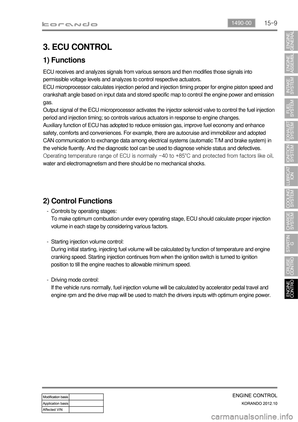
3. ECU CONTROL
1) Functions
ECU receives and analyzes signals from various sensors and then modifies those signals into
permissible voltage levels and analyzes to control respective actuators.
ECU microprocessor calculates injection period and injection timing proper for engine piston speed and
crankshaft angle based on input data and stored specific map to control the engine power and emission
gas.
Output signal of the ECU microprocessor activates the injector solenoid valve to control the fuel injection
period and injection timing; so controls various actuators in response to engine changes.
Auxiliary function of ECU has adopted to reduce emission gas, improve fuel economy and enhance
safety, comforts and conveniences. For example, there are autocruise and immobilizer and adopted
CAN communication to exchange data among electrical systems (automatic T/M and brake system) in
the vehicle fluently. And the diagnostic tool can be used to diagnose vehicle status and defectives.
<00760097008c00990088009b00900095008e0047009b008c00940097008c00990088009b009c0099008c0047009900880095008e008c00470096008d0047006c006a007c00470090009a0047009500960099009400880093009300a000470054005b005700
47009b009600470052005f005c00b6006a004700880095008b> protected from factors like oil,
water and electromagnetism and there should be no mechanical shocks.
2) Control Functions
Controls by operating stages:
To make optimum combustion under every operating stage, ECU should calculate proper injection
volume in each stage by considering various factors.
Starting injection volume control:
During initial starting, injecting fuel volume will be calculated by function of temperature and engine
cranking speed. Starting injection continues from when the ignition switch is turned to ignition
position to till the engine reaches to allowable minimum speed.
Driving mode control:
If the vehicle runs normally, fuel injection volume will be calculated by accelerator pedal travel and
engine rpm and the drive map will be used to match the drivers inputs with optimum engine power. -
-
-
Page 480 of 1082

15-150000-00
(4) Features
Determines the ignition timing according to input signal
The ECU always analyzes the following elements when determining the ignition timing. 1.
Crankshaft position sensor
Camshaft position sensor
Coolant temperature sensor
Intake air temperature/air mass -
-
-
-
Warm-up of catalytic converter
The ignition timing is retarded for about 20 seconds to operate the catalytic converter according to the
operating temperature under the following conditions: 2.
<007b008f008c0047008a00960096009300880095009b0047009b008c00940097008c00990088009b009c0099008c00470090009a00470058005c00b6006a004700a50047005b005700b6006a00470088009b0047009a009b00880099009b00900095008e00
55>
The idle speed is increased by the idle speed control to help warming up of the catalytic converter -
-
Idle speed control
<007b008f008c00470090008e00950090009b0090009600950047009b0090009400900095008e0047008a0088009500470089008c00470099008c009b00880099008b008c008b0047009c00970047009b00960047005a005d00b60047009600990047008800
8b009d00880095008a008c008b0047009c00970047009b0096> 20˚ to help idle speed control.
The ignition timing control can be performed faster than the control through the throttle valve.
Fuel cut-off in deceleration
The ignition timing is retarded temporarily to prevent abrupt increase of the torque when the
combustion is restarted.
Intake air temperature/coolant temperature
The ignition timing is retarded to prevent knocking if the intake air temperature or coolant temperature
is high. The ignition timing is retarded in the following cases. 3.
4.
5.
The intake air temperature is above 30°C.
The coolant temperature is above 105°C. -
-
The ignition timing retard for intake air temperature and for coolant temperature is added up for
correction.
ESP/ASR control mode
The ignition timing is retarded to reduce engine torque as fast as possible under the ESP/ASR
control mode.
Knocking control
If knocking occurs in the cylinder, the ignition angle of the corresponding cylinder is retarded. The
coolant temperature is 15˚C to 40˚C when starting. 6.
7.
Page 488 of 1082

15-230000-00
8) CAN Configuration (P-CAN/B-CAN)
(1) CAN Configuration (P-CAN/B-CAN)
Name Function
ECUElectronic Control Unit
TCUTransmission Control Unit
EPSElectronic Power Steering Unit
BCMBody Control Moudule
SKMSmart Key Moudule
CAN system communicates with the system units in vehicle. It consists of P-CAN and B-CAN according
to the communication speed.
P-CAN & B-CAN: SKM, Instrument cluster, BCM, Disgnostic connector
P-CAN: ECU, ABS & ESP, TCU, E-coupling, EPS unit
Terminal resistance: installed on ECU and BCM
Page 627 of 1082

03-618710-01
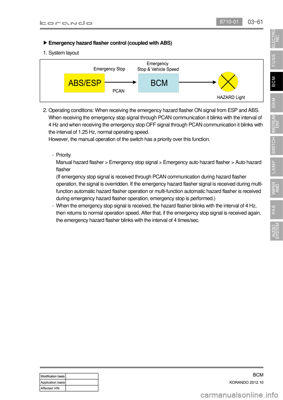
Emergency hazard flasher control (coupled with ABS) ▶
System layout 1.
Operating conditions: When receiving the emergency hazard flasher ON signal from ESP and ABS.
When receiving the emergency stop signal through PCAN communication it blinks with the interval of
4 Hz and when receiving the emergency stop OFF signal through PCAN communication it blinks with
the interval of 1.25 Hz, normal operating speed.
However, the manual operation of the switch has a priority over this function. 2.
Priority
Manual hazard flasher > Emergency stop signal > Emergency auto hazard flasher > Auto hazard
flasher
(If emergency stop signal is received through PCAN communication during hazard flasher
operation, the signal is overridden. If the emergency hazard flasher signal is received during multi-
function automatic hazard flasher operation or multi-function automatic hazard flasher is received
during emergency hazard flasher operation, emergency stop is performed.)
When the emergency stop signal is received, the hazard flasher blinks with the interval of 4 Hz,
then returns to normal operation speed. After that, if the emergency stop signal is received again,
the emergency hazard flasher blinks with the interval of 4 times/sec. -
-
Page 643 of 1082

04-98712-03
Passive function actuation area: Within 1 m from the door handle
Passive tailgate open actuation area: Within 1 m from the bumper -
-Response signal
(RF transmission) Verification request signal
(LF transmission)Smart key
Passive function
operating range
Passive
trunk open
operating range
Passive function
operating range
2) Smart Key Function
(1) Passive entry actuation area
Passive entry actuation area ▶Searching for a smart key signal from the outside the vehicle is prioritized in theft deterrent mode.
Searching for a smart key signal from the inside is prioritized when the theft deterrent mode is
deactivated.
The smart key verification is performed only for the driver's or passenger's door which has received
the input from the corresponding door handle switch. If a verified smart key is found, the passive entry
function is performed.
A maximum of 3 keys can be registered. -
-
- The passive LOCK/UNLOCK is performed by the input from the outside door handle switch.
(For driver's door LOCK/UNLOCK)
Page 645 of 1082

04-118712-03
(2) Passive LOCK
When the system searches for a smart key by the input from the outside door handle switch, the SKM
sends the passive LOCK signal to the BCM if all the doors are closed and a normal smart key is found
outside the vehicle.
Passive LOCK hardware control ▶
The SKM sends the door LOCK/UNLOCK signal to the BCM through the BCAN network when a
smart key is verified after the signal from the driver/passenger outside door handle switch is received
through the hardware.
The SKM sends the signal to the BCM and instrument cluster when the warning and indicator
display conditions are met. 1.
2.
Passive LOCK by outside door handle switch ▶
When the ignition status is OFF, ACC ON or IGN ON, the SKM performs the verification procedure if the
LOCK signal is received from the driver/passenger door handle switch.
When the outside door handle switch is operated, the SKM verifies if a smart key is outside the
vehicle using the corresponding exterior antenna.
The SKM sends the signal for [Passive LOCK command] to the BCM through the BCAN if a smart
key is identified as being outside the vehicle.
If no smart key is verified as being outside the vehicle, this process is stopped and restarted when the
next signal is received from the outside door handle switch.
When the driver's door is unlocked with the ignition status ACC ON, the SKM changes the ignition
status to OFF and sends the signal for [Passive LOCK command] to the BCM through the BCAN to
lock the door. The BCM ignores the signal if the ignition status is IGN ON.
The SKM recovers the deactivated smart key function inside the vehicle when it receives the theft
deterrent deactivation signal from the BCM through the BCAN communication. 1.
2.
3.
4.
-
Page 647 of 1082

04-138712-03
(3) Passive UNLOCK
When the system searches for a smart key by the input from the outside door handle switch, the SKM
sends the passive UNLOCK signal to the BCM if all the doors are closed and a normal smart key is
found outside the vehicle.
Passive UNLOCK hardware control ▶
The SKM sends the door LOCK/UNLOCK signal to the BCM through the BCAN network when a
smart key is verified after the signal from the driver/passenger outside door handle switch is received
through the hardware. 1.
Passive UNLOCK by outside door handle switch ▶
When the ignition status is OFF, ACC ON or IGN ON, the SKM starts to verify the smart key if below
conditions are met.
When the driver or passenger door handle switch is operated, the SKM verifies if a smart key is outside
the vehicle using the corresponding antenna.
When the outside door handle switch is operated, the SKM verifies if a smart key is outside the
vehicle using the corresponding exterior antenna.
The SKM sends the signal for [Passive UNLOCK command] to the BCM through the BCAN if a
smart key is identified as being outside the vehicle.
If no smart key is identified as being outside the vehicle, this process is stopped and restarted when
the next signal is received from the outside door handle switch.
When the driver's door is locked with the ignition status ACC ON or IGN ON, the SKM sends the
signal for [Passive UNLOCK command] to the BCM through the BCAN to unlock the door without
changing the ignition status to OFF. 1.
2.
3.
4.
Smart key search mode ▶
The system first identifies the last smart key used, and then identifies all the other registered smart
keys until a normal smart key is verified.
The system identifies the smart keys by using the outside door handle antenna on the door handle
switch which has sent the signal.
Smart key search input: The last door is opened and then closed. Outside door handle switch, Brake
switch, START switch (Tailgate open request)
Exceptional mode
When operating the door handle switch, the system changes the smart key searching conditions in
vehicle inside and outside according to the theft deterrent mode.
- Searching sequence when disarmed by BCM: Inside > Outside
- which function is restricted when the BCM is in theft deterrent mode. 1.
2.
3.
4.