Page 888 of 1082
03-33190-01
1. SPECIFICATION
DG20DD
Model name WM6F1
Overall length 370 mm
Distance between shafts 205 mm / 70 mm
Weight (except transmission fluid) 62 kgf (2WD) / 63 kgf (4WD)
Gear ratio 1st 3.538 3.385 3.616
2nd 1.909 1.708 1.957
3rd 1.179 1.033 1.207
4th 0.814 0.786 0.905
5th 0.734 0.730 0.842
6th 0.628 0.595 0.714
Reverse 3.910 3.747 3.747
Synchronizer ring
type1st T: Triple-cone
2nd T: Triple-cone
3rd T: Triple-cone
4th D: Double-cone
5th D: Double-cone
6th S: Single-cone
Reverse T: Triple-cone
Shifting Type Remote (Cable type)
Gear selector lever
positionReversing:
Reverse ring
pull type
ItemSpecification
Remark
D20DTFD20DTF +
Low CO₂G20DF
Page 899 of 1082
04-30000-00
1. SPECIFICATION
Description Specification
Operating type Hydraulic type
Clutch cover Type Diaphragm spring strap
Adjusting type SATIC (Self Adjusting Technology with
Integrated Cassette) type
Clutch pedal Type Suspended type
Max. operating travel135 ± 3 mm
Pedal free play (Longitudinal)7.1 ± 3 mm
Pedal free play (Transverse) 3 mm
Clutch disc Type Dry type single diaphragm (Rigid type)
Diameter of facingOuter: 250 ± 1 mm
Inner:160 ± 0.8 mm
Thickness of discFree: 8.7 ± 0.3 mm
When loaded: 8.0 ± 0.2 (at 7,800 N)
Numbers of disc 2
Weight 1.18 kg
Flywheel type DMF (Dual Mass Flywheel)
Setting load of clutch cover assembly At least 7,800 N
Clutch master cylinder Operating travel 30 mm
Inner diameter 17.46 mm
Concentric slave
cylinderMaximum operating travel 12.55 mm
Operating pressure Maximum 50 bar
Standard DOT 3 or DOT 4
Capacity As required
Clutch oil
Page 906 of 1082
05-33310-02
1. SPECIFICATION
Description Specification
Structure 2-piece type with CV joint, spider, and rubber
coupling
Weight below 12.0 kg
Joint type CV joint, spider, rubber coupling
Spider Numbers one (installed on center bearing side)
External diameterØ24 mm
Overall sizeØ62.5 mm
Dimension
(Length x Dia.)No.1 shaft (TM to spider)1,069 x Ø60 mm
No. 2 shaft (spider to axle)847.5 x Ø60 mm
Runout of tube (after installation) 0.3 mm
Unbalance 80g.mm @ 3,000rpm
(second measurement: 120 g.mm)
U-joint Starting torque 0.3 to 0.7 Nm
Minimum starting angle18˚
Amount of grease in CV joint 210+-10g
2. TIGHTENING TORQUE
Fastener Tightening torque
Bolt/nut for rubber coupling (rear axle side) 39.2 to 49.0 Nm
Bolt/nut for CV joint (transaxle side) 29.4 to 39.2 Nm
Mounting bolt for center bearing 58.8 to 68.6 Nm
Page 908 of 1082
05-53310-02
2. COMPONENT
1 End cap 18 Plain washer
2 VL joint assembly 19 AL washer
3 Washer 20 Center bearing assembly
4 Bolt 21 Ball bearing
5 Circlip 22 Dust shield
6 Clamp (big) 23 Intermediate shaft
7 Boot 24 Fork yoke
8 Clamp (small) 25 Rubber coupling
9 Stub shaft 26 Alignment support
10 Bending absorber 27 Bolt
11 Paper damper 28 Washer
12 Tube yoke 29 Lock nut
13 Oil seal 30 Balance weight
14 Spider 31 Protecter
15 Bearing cap 32 Tube
16 Intermediate yoke 33 Tube
17 Bolt 34 Bending absorber
Do not remove the rubber coupling since the vibration balance could be improper once removed it.
Page 913 of 1082
07-30000-00
1. SPECIFICATION
Unit Description Specification
PTU
(Power Transfer Unit)Gear ratio 2.929
Numbers of helical gear 22/39
Numbers of hypoid gear 23/38
Oil IDEMITSU LW 80W/90
Oil capacity≒ 0.58 L
Operating temperature-40 to 150°C
E-coupling Maximum torque 1,000 Nm
Operating temperature-40 to 120°C
Numbers of main clutch Outer: 11, Inner: 11
Numbers of pilot clutch Outer: 4, Inner: 3
Coil windings 240 turns
Weight 8 kg
Oil ECF107 (ATF based EMCD special oil)
Oil capacity 0.145 L (145 ml)
Page 921 of 1082

08-8
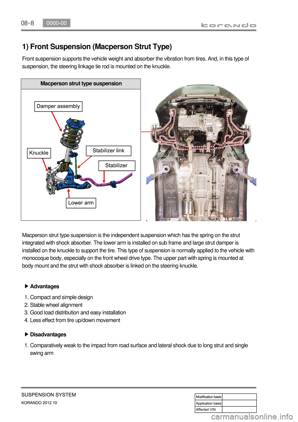
1) Front Suspension (Macperson Strut Type)
Front suspension supports the vehicle weight and absorber the vibration from tires. And, in this type of
suspension, the steering linkage tie rod is mounted on the knuckle.
Macperson strut type suspension is the independent suspension which has the spring on the strut
integrated with shock absorber. The lower arm is installed on sub frame and large strut damper is
installed on the knuckle to support the tire. This type of suspension is normally applied to the vehicle with
monocoque body, especially on the front wheel drive type. The upper part with spring is mounted at
body mount and the strut with shock absorber is linked on the steering knuckle.
Advantages ▶
Compact and simple design
Stable wheel alignment
Good load distribution and easy installation
Less effect from tire up/down movement 1.
2.
3.
4.
Disadvantages ▶
Comparatively weak to the impact from road surface and lateral shock due to long strut and single
swing arm 1.
Macperson strut type suspension
Page 922 of 1082
08-90000-00
2) Rear Suspension (Multi-link Type)
Multi-link type suspension is the independent suspension. It provides good ride comfort and drivability by
reducing the coil spring weight. Also, it increases the space for passenger compartment by lowering the
floor.
This type of suspension consists of multiple links such as trailing arm, upper arm, lower arm and track
rod.
Layout
Page 944 of 1082

10-134890-00
2) Basic Theory of ABS Function
To give you a better understanding of the tasks and functions of ABS, we will first look at the physics
principles.
(1) Stopping distance
The stopping distance depends on the vehicle weight and initial speed when braking starts. This also
applies for vehicle with ABS, where ABS always tries to set an optimum brake force on each wheel. As
great forces are exerted between the tires and the carriageway when braking, even with ABS the wheels
may scream and rubber is left on the road. With an ABS skid mark one may be able to clearly recognize
the tire profile. The skid mark of an ABS vehicle does not however leave any hint of the speed of the
vehicle in the case of an accident, as it can only be clearly drawn at the start of braking.
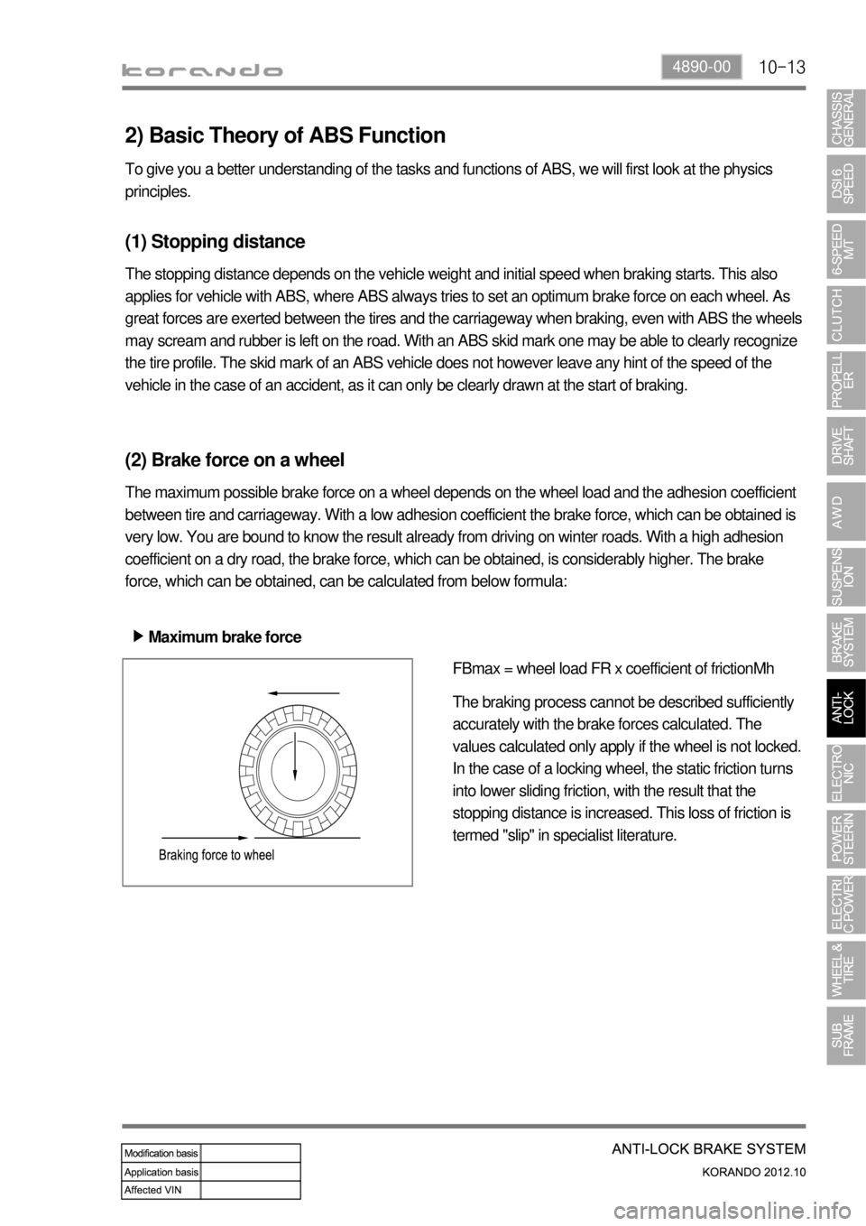
(2) Brake force on a wheel
The maximum possible brake force on a wheel depends on the wheel load and the adhesion coefficient
between tire and carriageway. With a low adhesion coefficient the brake force, which can be obtained is
very low. You are bound to know the result already from driving on winter roads. With a high adhesion
coefficient on a dry road, the brake force, which can be obtained, is considerably higher. The brake
force, which can be obtained, can be calculated from below formula:
Maximum brake force ▶
FBmax = wheel load FR x coefficient of frictionMh
The braking process cannot be described sufficiently
accurately with the brake forces calculated. The
values calculated only apply if the wheel is not locked.
In the case of a locking wheel, the static friction turns
into lower sliding friction, with the result that the
stopping distance is increased. This loss of friction is
termed "slip" in specialist literature.