Page 513 of 1082
14-70000-00
Measuring the voltage drop between lines ▶
Measure the voltage drop between alternator B+ and battery B+. -
Specified valuebelow 0.3V
If the value is out of the specified value, check the terminal and clamp for looseness.
Checking the charge warning lamp ▶
<007b009c0099009500470096008d008d00470088009300930047008c0093008c008a009b00990090008a0047008b008c009d0090008a008c009a004700880095008b00470097009c009b0047009b008f008c00470090008e00950090009b00900096009500
47009a009e0090009b008a008f004702c80076007502c90047>(Pre-warning).
Check if the charge warning lamp goes out.
If the charge warning lamp does not go off, inspect the electric circuit.
Start the engine and check if the charge warning lamp keeps off. 1.
2.
-
3.
Page 521 of 1082
14-150000-00
8. DTC SETTING CONDITIONS
Charge warning lamp ON condition ▶
Turn the ignition ON (Engine stopped)
Open or short circuit of L terminal wiring, open or short internal circuit of alternator (fixed control of
13.8V)
Open or short circuit of F terminal wiring, no feedback output signal 1.
2.
3.
Page 522 of 1082
14-16
1. LAYOUT
D20DTF(Low CO2) D20DTF
ECUBattery sensor (EBS)
Alternator (ALT)
Meter cluster (charge
warning lamp)
Page 524 of 1082
14-18
Operation of charge warning lamp ▶
ECU checks the generating voltage from alternator and circuit conditions and sends the warning lamp ON
signal to meter cluster through CAN line.Basic control logic according to the driving conditions ▶
Engine ECU determines the engine loads according to the fuel injection volume and engine speed. It
charges the battery by increasing the generating voltage during deceleration. To improve the fuel
economy by reducing the alternator load during acceleration, engine ECU decreases the generating
voltage and consumes the battery voltage.
Page 525 of 1082
14-190000-00
3. CAN COMMUNICATION (Charge Warning Lamp)
Overview ▶
Meter cluster
(charge warning lamp)
The meter cluster receives the charge warning lamp ON signal from ECU through CAN line.
Charge warning lamp ON conditions
Pre-warning
When DTC related EEM set
Open or short circuit in alternator -
-
-
Circuit diagram ▶
Page 532 of 1082
01-8
Steering wheel remote
control switchPassenger door switch
Lower main panel
switch
Start/stop switch
Cruise control switch
Hazard warning switch
bezel assembly
Multifunction switch
FATC switch
Drive door main switch
& Outside rearview mirror
switch
3. SWITCH SYSTEM LAYOUT
Page 570 of 1082
03-4
2. FUNCTIONS
1) Functional List
FunctionSKM
without
BCMSKM
with
BCM
1 Wiper control Wiper mist & washer coupled wiper O O
Auto washer coupled wiper O O
Auto light-rain sensor coupled wiper (LIN) O O
Speed sensitive intermittent wiper O O
Wiper low/high control O O
2 Key reminder warning Key reminder warning O X
Ignition key reminder O X
External buzzer control X O
Anti-lock function when opening door O O
3 Tail lamp control Tail lamp ON warning O O
External lamp warning display X O
Tail lamp auto OFF O O
4 Door ajar warning Door status management X O
Door ajar warning O O
5 Seat belt control Seat belt warning O O
Seat belt reminder O O
6 Sunroof warning Sunroof warning control O O
Sunroof warning display X O
7 Room lamp control Door coupled room lamp and dimming control O O
Room lamp OFF control O O
Room lamp control display X O
8 Key hole illumination
controlKey hole illumination O X
9 Defogger (heated wire)
controlFront defogger timer O O
Rear defogger timer
OO
Page 572 of 1082

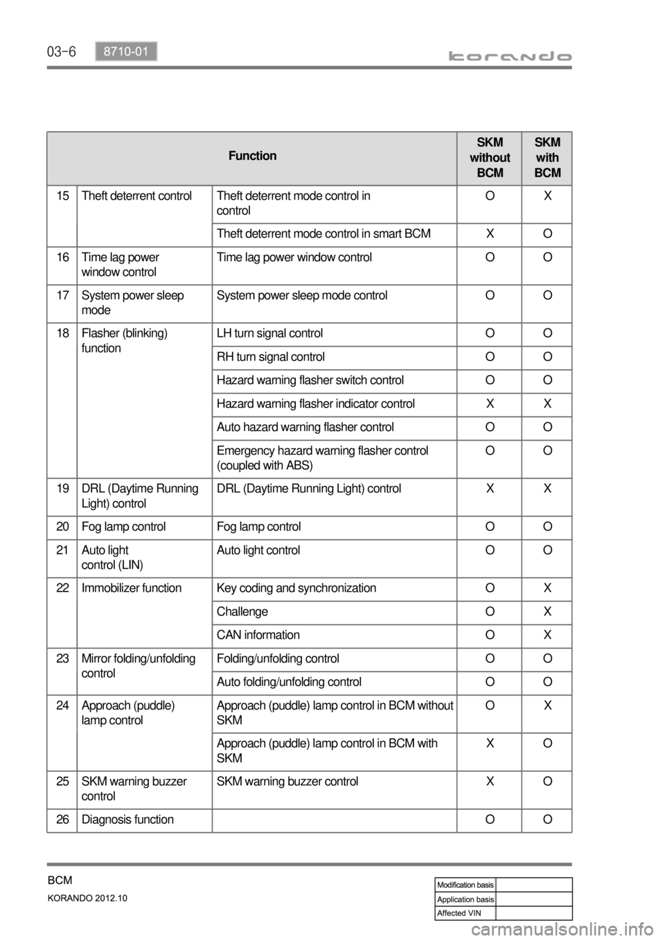
03-6
FunctionSKM
without
BCMSKM
with
BCM
15 Theft deterrent control Theft deterrent mode control in
controlOX
Theft deterrent mode control in smart BCM X O
16 Time lag power
window controlTime lag power window control O O
17 System power sleep
modeSystem power sleep mode control O O
18 Flasher (blinking)
functionLH turn signal control O O
RH turn signal control O O
Hazard warning flasher switch control O O
Hazard warning flasher indicator control X X
Auto hazard warning flasher control O O
Emergency hazard warning flasher control
(coupled with ABS)OO
19 DRL (Daytime Running
Light) controlDRL (Daytime Running Light) control X X
20 Fog lamp control Fog lamp control O O
21 Auto light
control (LIN)Auto light control O O
22 Immobilizer function Key coding and synchronization O X
Challenge O X
CAN information O X
23 Mirror folding/unfolding
controlFolding/unfolding control O O
Auto folding/unfolding control O O
24 Approach (puddle)
lamp control
Approach (puddle) lamp control in BCM without
SKMOX
Approach (puddle) lamp control in BCM with
SKMXO
25 SKM warning buzzer
controlSKM warning buzzer control X O
26 Diagnosis function O O