Page 838 of 1082

02-4
The shiftable gear can be adjusted by pressing the
"UP (D+)" or "DOWN(D-)" switch when the gear
selector lever is in “M” position.
Shift lock release button
If the selector lever cannot be moved from
“P” or “N” position, try to move the lever
while pushing down this button with finger. For
safety, turn off the engine and depress the
brake pedal before the attempt.
Shift up Shift down Tip switches on steering wheel ▶
Meter cluster ▶
This indicator shows the current position of
the gear.
Gear selector lever ▶
Lever positions
P : Park
R : reverse
N : Neutral
D : Drive
Mode switch
W: Winter mode (pressed "OUT")
S: Standard mode (pressed "IN")
Toggle the mode between winter mode
and standard mode by pressing this
switch.Tip switch (manual shift switch)
The shiftable gear can be adjusted by
moving this switch to forward and rearward
when the gear selector lever is in “M”
position.
Selection of Manual/Automatic Shift Function
D: Automatic shift according to the driving condition
M: Manual shift
Page 847 of 1082

02-133680-01
4. LIMP HOME MODE
When the transaxle is defective ▶
In the event of a system fault, the TCU also provides for failure mode effect control (FMEC) to maintain
maximum functional operation of the transaxle.
In the event of a total loss of control or electrical power, the basic transaxle functions (Park, Reverse,
Neutral and Drive) are retained. The 4th and reverse gear ratios with the torque converter clutch in the
unlocked state are the retained gear states the hydraulic system supports without any electrical
assistance.
The TCU communicates with other vehicle electronic control modules by the controller area network
(CAN). If a major fault develops, the transaxle may automatically operate in a "limp home" (failure)
mode to enable the vehicle to be driven to an authorized dealer for repair.
The TCU also provides for transaxle diagnostics, which meet the requirements of OBD II legislation,
monitoring all components which may effect vehicle emissions. 1.
2.
3.
4.
When the transaxle overheats ▶
Limp home mode may also be engaged if the battery charge falls below 8V.
If the transaxle overheats, the shift patterns will automatically change to enable improved transaxle
cooling.
During transaxle overheat, the instrument cluster transaxle selector position display and the over
<009b008c00940097008c00990088009b009c0099008c0047008a00960095008b0090009b00900096009500470090009a004700900095008b0090008a0088009b008c008b0047008900a00047008d00930088009a008f00900095008e0047009b008f008c00
4702c8007e004f007e00900095009b008c0099005002c90047>indicator on the instrument
cluster until normal transaxle operating temperature is reached. 1.
2.
3.
Towing the automatic transaxle equipped vehicle ▶
Flat-bed equipment is the best method of moving a disabled vehicle to avoid any damages.
For AWD vehicle: The vehicle must be towed with a wheel lift and dollies or flatbed equipment with
all the wheels off the ground.
For 2WD vehicles: It is acceptable to tow the vehicle with the rear wheels on the ground without
dollies and the front wheels off the ground. When being towed by a commercial towtruck and wheel
dollies are not available, the front of the vehicle should be lifted, not the rear. -
-
Page 865 of 1082
03-53660-01
The shiftable gear can be adjusted by pressing the
"UP (D+)" or "DOWN(D-)" switch when the gear
selector lever is in “M” position.
Shift lock release button
If the selector lever cannot be moved from
“P” or “N” position, try to move the lever
while pushing down this button with finger. For
safety, turn off the engine and depress the
brake pedal before the attempt.
Shift up Shift down Tip switches on steering wheel ▶
Meter cluster ▶
This indicator shows the current position of
the gear.
Gear selector lever ▶
Lever positions
P : Park
R : reverse
N : Neutral
D : DriveTip switch (manual shift switch)
The shiftable gear can be adjusted by
moving this switch to forward and rearward
when the gear selector lever is in “M”
position.
Selection of Manual/Automatic Shift Function
D: Automatic shift according to the driving condition
M: Manual shift
Page 876 of 1082

03-16
4. LIMP HOME MODE
When the transaxle is defective ▶
In the event of a system fault, the TCU also provides for failure mode effect control (FMEC) to maintain
maximum functional operation of the transaxle. (There are 3 FMEC modes, mechanical limp-home
mode, electrical limp-home mode, limp-home mode C.)
In the event of a total loss of control or electrical power, the basic transaxle functions (Park, Reverse,
Neutral and Drive) are retained. The 4th and reverse gear ratios with the torque converter clutch in the
unlocked state are the retained gear states the hydraulic system supports without any electrical
assistance. (Mechanical limp-home)
If the speed sensor circuit is failed, the gear is fixed to 4th gear, but manual shifting
<004f00590095008b02e9005a0099008b02e9005b009b008f005000470090009a00470088009d008800900093008800890093008c0055004f006c0093008c008a009b00990090008a00880093004700930090009400970047008f00960094008c0047009400
96008b008c0050>
If the inhibitor switch signals are invalid, shifting to1st and 2nd gear is forbidden. (Limp-home C)
The TCU communicates with other vehicle electronic control modules by the controller area network
(CAN). If a major fault is developed, the transaxle may not accomplish the intelligent shift control. The
TCU controls the transaxle with preset values.
The TCU also provides for transaxle diagnostics, which meet the requirements of OBD II regulation,
monitoring all components which may effect vehicle emissions. 1.
2.
3.
4.
5.
6.
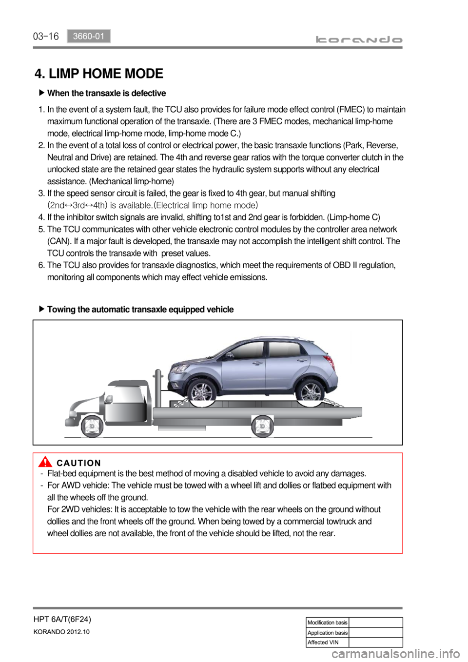
Towing the automatic transaxle equipped vehicle ▶
Flat-bed equipment is the best method of moving a disabled vehicle to avoid any damages.
For AWD vehicle: The vehicle must be towed with a wheel lift and dollies or flatbed equipment with
all the wheels off the ground.
For 2WD vehicles: It is acceptable to tow the vehicle with the rear wheels on the ground without
dollies and the front wheels off the ground. When being towed by a commercial towtruck and
wheel dollies are not available, the front of the vehicle should be lifted, not the rear. -
-
Page 903 of 1082

04-70000-00
Operating Elements ▶
The clutch "release" system consists of the clutch pedal and clutch release cylinder.
This system directly releases the clutch by using hydraulic pressure while the conventional clutch system
releases the clutch by using release lever and release fork. This system provides higher efficiency than
conventional clutch system, and its durability is superior.
Clutch master cylinder (mounted on clutch pedal)
Concentric slave cylinder pipe (mounted inside of transmission) -
-Driving elements ▶
The driving elements consist of two flat surfaces machined to a smooth finish.
One of these is the rear face of the engine flywheel and the other is the clutch pressure plate. The clutch
pressure plate is fitted into a clutch steel cover, which is bolted to the flywheel.
Driven elements ▶
The driven element is the clutch disc with a splined hub which is free to slide lengthwise along the splines
of the input shaft.
The driving and driven elements are held in contact by spring pressure. This pressure is exerted by a
diaphragm spring in the clutch cover pressure plate assembly.
2) Overview
Page 912 of 1082
06-6
3. REAR AXLE
The rear axle installed in this car is a removable axle, called IRDA (Independent Rear Differential Axle).
The rear differential carrier is installed directly on the sub frame,
and there is an independent suspension that allows each wheel on the same axle to move vertically and
independently of each other with the universal joint and the slip joint.
Page 914 of 1082
07-4
1. OVERVIEW
The AWD system in this vehicle is the electronic 4WD system and controls the traction to rear wheels
according to the driving conditions.
1) Driving Mode
(1) AUTO mode (Normal driving mode)
Normally the vehicle is in 2WD mode.
Automatically change to this mode when the vehicle needs higher traction.
(2) LOCK mode (when pressing 4WD LOCK switch)
This mode provides the highest traction. Use
this mode when driving on unpaved, rugged,
steep, sandy, wet or slippery roads.
In 4WD LOCK mode, if the rear wheel speed
exceeds 40 km/h, 4WD LOCK mode is
canceled and 4WD AUTO mode is activated
(Indicator OFF). If the speed is decreased
below 35 km/h, 4WD LOCK mode is resumed
(Indicator ON again). -
-
Mode table ▶
4WD LOCK switch Vehicle speed Driving mode
Not pressed (4WD AUTO) No conditions 4WD AUTO
Pressed (4WD LOCK) over 40 km/h 4WD AUTO
Pressed (4WD LOCK) below 35 km/h 4WD LOCK
Page 915 of 1082
07-50000-00
2. SYSTEM LAYOUT
1) Components
(1) PTU (Power Transfer Unit)
<007b008f008c004700970096009e008c00990047009b009900880095009a008d008c00990047009c00950090009b0047009000950047009b008f008c0047008d009900960095009b0047009e008f008c008c00930047008b00990090009d008c0047009400
96008b008c00930047008a008f00880095008e008c009a0047>the angle of engine torque to 90°
and transfer it to E-coupling to distribute the torque to rear wheels.
(2) E-Coupling (Electronic Coupling)
E-Coupling transfer the engine torque from PTU to rear axle and controls to distribute it between front
wheels and rear wheels.
(3) E-Coupling Control Unit (ECU)
E-Coupling controls the current (clutch engagement force) of EMCD in E-Coupling according to CAN
signals (wheel speed, engine torque, pedal position, ABS/ESP signals).
* EMCD: Electro-Magnetic Control Device PTU assemblyE-coupling control unit
(located on the floor under driver seat)E-coupling