Page 961 of 1082
11-90000-00
4. WARNING LAMPS
1) ABS
ABS warning lamp module indicates the self-diagnosis and malfunction.
ABS warning lamp ON: Warning Lamp
When turning the ignition switch to ON position, ABS warning lamp comes on for 3 seconds for self-
diagnosis and goes off if the system is OK (initialization mode).
When the system is defective, the warning lamp comes on.
When the self-diagnosis is performing, the warning lamp comes on.
When the HECU connector is disconnected, the warning lamp comes on.
ABS is not available during lamp ON. In this condition, Only normal brake system without ABS
function is available.
When the communication between warning lamp CAN module in meter cluster, the warning lamp
comes on. 1.
2.
3.
4.
5.
6.ABS warning lamp
Brake warning lamp
ESP OFF indicator
ESP warning lamp/indicator
EBD warning lamp 1.
2.
3.
4.
5.
Page 962 of 1082

11-10
2) EBD (Electronic Brake-force Distribution) Warning Lamp (Brake
Warning Lamp)
EBD warning lamp when the system perform the self diagnosis and when it detects the malfunction of
EBD system. However, the brake warning lamp comes on regardless of EBD when the parking brake is
applied.
EBD warning lamp ON:
When turning the ignition switch to ON position, ABS warning lamp and the brake warning lamp
comes on for 3 seconds for self diagnosis and goes off if the system is OK (initialization mode).
When applying the parking brake, the brake warning lamp comes on.
When the brake fluid is not sufficient, the brake warning lamp comes on.
When the self-diagnosis is performing, the warning lamp comes on.
When the HECU connector is disconnected, the warning lamp comes on.
When the system is defective, ABS warning lamp and the brake warning lamp come on
simultaneously. 1.
2.
3.
4.
5.
6.
When the solenoid valve is defective
When one or more wheel sensors are defective
When ABS HECU is defective
When the voltage is abnormal
When valve relay is defective a.
b.
c.
d.
e.
When the communication between warning lamp CAN module in meter cluster, the warning lamp
comes on. 7.
3) ESP OFF Indicator
ESP OFF indicator ON:
When turning the ignition switch to ON position, ESP warning lamp comes on for 3 seconds for self
diagnosis and goes off if the system is OK (initialization mode).
When the ESP OFF switch is pressed to turn off ESP function, ESP OFF indicator comes on. 1.
2.
4) ESP Warning Lamp
ESP warning lamp ON:
When turning the ignition switch to ON position, ESP warning lamp comes on for 3 seconds for self
diagnosis and goes off if the system is OK (initialization mode).
When the system is defective, the warning lamp comes on.
When the ESP function is activated, ESP warning lamp blinks with the interval of 2 Hz.
When the communication between warning lamp CAN module in meter cluster, the warning lamp
comes on. 1.
2.
3.
4.
5.
5) ESP OFF Switch
If ESP OFF switch is pressed, ESP function is deactivated and the ESP OFF indicator in the instrument
cluster comes on.
To resume the ESP function, press the switch again. At this time, ESP OFF indicator goes out.
Page 1019 of 1082
02-38810-00
1. SPECIFICATIONS
Operating voltage 9 to 16 V
System diagnosis and SDM self diagnosis voltage 9 to 16 V
Ignition voltage for side air bag and pretensioner 9 to 16 V
Communication voltage for front impact sensor 9 to 16 V
Communication voltage for side impact sensor 9 to 16 V
Operating temperature -40℃ ~ 85℃
Storage temperature -40℃ ~ 90℃
Ignition temperature -30℃ ~ 85℃
Overvoltage protection 24 V
2. MAJOR REPLACEMENT PARTS AFTER AIR BAG
DEPLOYMENT
A. In Case Of Front Air Bag Deployment
Air bag unit and its wirings (including connectors), seat belt pretensioner and its wirings (including
connectors), all front air bags, instrument panel, front impact sensor and other damaged components
B. In Case Of Curtain Air Bag Deployment
Deployed curtain air bag, air bag unit and its wiring (including connector), impact G sensor assembly for
curtain air bag, damaged trim, seat and roof headlining
Page 1024 of 1082

02-8
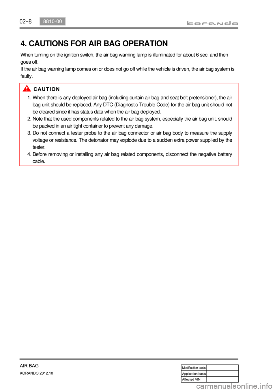
4. CAUTIONS FOR AIR BAG OPERATION
When there is any deployed air bag (including curtain air bag and seat belt pretensioner), the air
bag unit should be replaced. Any DTC (Diagnostic Trouble Code) for the air bag unit should not
be cleared since it has status data when the air bag deployed.
Note that the used components related to the air bag system, especially the air bag unit, should
be packed in an air tight container to prevent any damage.
Do not connect a tester probe to the air bag connector or air bag body to measure the supply
voltage or resistance. The detonator may explode due to a sudden extra power supplied by the
tester.
Before removing or installing any air bag related components, disconnect the negative battery
cable. 1.
2.
3.
4. When turning on the ignition switch, the air bag warning lamp is illuminated for about 6 sec. and then
goes off.
If the air bag warning lamp comes on or does not go off while the vehicle is driven, the air bag system is
faulty.
Page 1028 of 1082
02-12
2. OPERATING CONDITIONS
1) Front Air Bag Operating Conditions When A Frontal Impact
Occurs
2) Side Air Bag Operating Conditions When A Side Impact Occurs
Impact to Left direction Right direction
Seat belt pretensioner - Driver side IGN IGN
Seat belt pretensioner - Passenger side IGN IGN
Side air bag module - Passenger side IGN Not ignite
Side air bag module - Passenger side Not ignite IGN
Inflatable curtain air bag module - Driver side IGN Not ignite
Inflatable curtain air bag module - Passenger side Not ignite IGN
Impact to Front side
Driver air bag IGN
Passenger air bag IGN
Seat belt pretensioner - Driver side IGN
Seat belt pretensioner - Passenger side IGN
Once the ignition starts, the SDM starts to diagnose the air bag system during the ignition process.
If the system is OK, the SDM is armed for a specific impact on the vehicle. The ignition time takes about
6 sec.
Page 1029 of 1082

02-138810-00
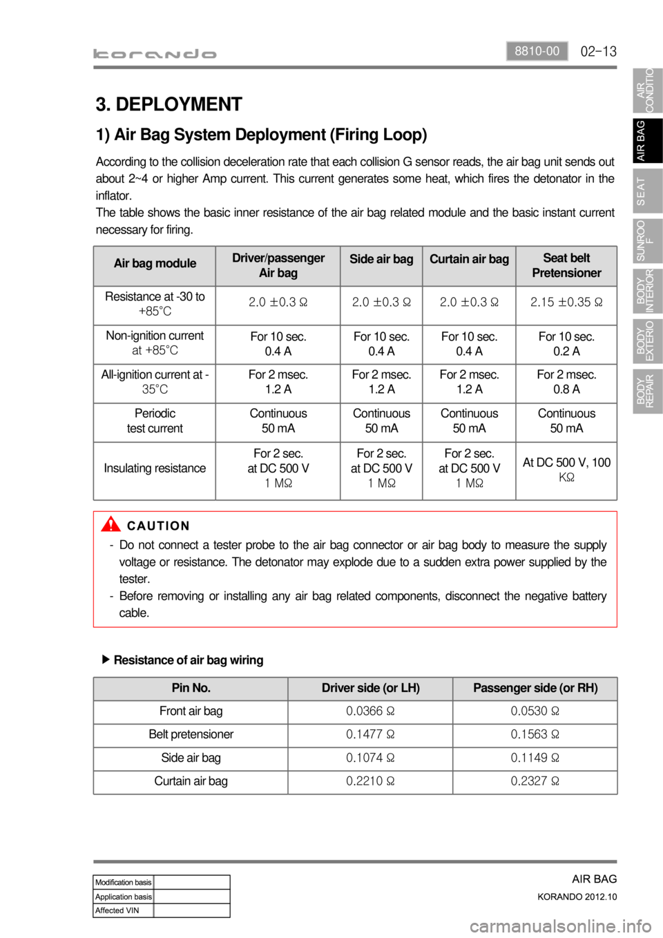
Air bag moduleDriver/passenger
Air bagSide air bag Curtain air bagSeat belt
Pretensioner
Resistance at -30 to
+85°C2.0 ±0.3 Ω 2.0 ±0.3 Ω 2.0 ±0.3 Ω 2.15 ±0.35 Ω
Non-ignition current
at +85°CFor 10 sec.
0.4 A For 10 sec.
0.4 AFor 10 sec.
0.4 AFor 10 sec.
0.2 A
All-ignition current at -
35°CFor 2 msec.
1.2 AFor 2 msec.
1.2 AFor 2 msec.
1.2 AFor 2 msec.
0.8 A
Periodic
test currentContinuous
50 mAContinuous
50 mAContinuous
50 mAContinuous
50 mA
Insulating resistanceFor 2 sec.
at DC 500 V
1 MΩFor 2 sec.
at DC 500 V
1 MΩFor 2 sec.
at DC 500 V
1 MΩ
At DC 500 V, 100
KΩ
3. DEPLOYMENT
According to the collision deceleration rate that each collision G sensor reads, the air bag unit sends out
about 2~4 or higher Amp current. This current generates some heat, which fires the detonator in the
inflator.
The table shows the basic inner resistance of the air bag related module and the basic instant current
necessary for firing.
1) Air Bag System Deployment (Firing Loop)
Do not connect a tester probe to the air bag connector or air bag body to measure the supply
voltage or resistance. The detonator may explode due to a sudden extra power supplied by the
tester.
Before removing or installing any air bag related components, disconnect the negative battery
cable. -
-
Pin No. Driver side (or LH) Passenger side (or RH)
Front air bag 0.0366 Ω 0.0530 Ω
Belt pretensioner 0.1477 Ω 0.1563 Ω
Side air bag 0.1074 Ω 0.1149 Ω
Curtain air bag 0.2210 Ω 0.2327 Ω
Resistance of air bag wiring ▶
Page 1032 of 1082
02-16
3) CAN Communication Interface (FIS and SIS)
The CAN communication interface uses the PWM for the supply current and the current loop and
communicates with the SDM to transmit the information. The serial communication and power for the
satellite are supplied through the communication line.
Stage FIS SIS
Initial stage Tracking/Check (Self test) Same as FIS
Normal operation Checks the FIS condition and sends the result as
"OK" or "NOK", and also sends the "severity" of the
crash. Same as FIS
Voltage The FIS hardware reset was performed under 5 V,
communication voltage low Same as FIS
Fault The fault is found in the current ignition cycle but the
fault is deactivated in the next ignition cycle. Multiple faults can be found
and deactivated in the same
ignition cycle.
The FIS moves to the initial stage if 'leakage to GND' is occurred in normal operating stage to shut down
the power and prevent abnormal operation.
※ FIS: Front Impact Sensor
SIS: Side Air bag Sensor
Page 1033 of 1082
02-178810-00
4. AIR BAG WARNING LAMP OPERATIONAL CONDITIONS
When there are no active and past faults ▶
The air bag warning lamp is operated as shown below if there is no fault occurred in the previous ignition
cycle and the SDM is running without any active fault right after starting the ignition cycle.
When there is no active fault and past faults occurred less than 10 times ▶
The warning lamp is operated as shown below every time the vehicle is started if the SDM is running
without any active fault in the entire time and past faults in the previous ignition cycle occurred within 10
times.
"Battery voltage too low" is not included in the past faults.