Page 793 of 1082
08-277810-00
For the vehicles without rain sensor, the BCM operates the wiper as follows:
When turning the ignition switch to ON from OFF position with the intermittent wiper switch in "ON"
position, the wipers do not operate.
When turning the wiper switch to ON from OFF position after turning the ignition switch to ON position,
the wipers operate one cycle.
The wiper's operation cycle depends on the vehicle speed (CAN communication with instrument
cluster) and wiping speed the side fascia panel.
<00540047007e0090009700900095008e0047008a00a0008a0093008c00610047005a004700b7004700570055005c0047009a008c008a00550047004f006d0068007a007b00500047009b0096004700580060004700b7004700590047009a008c008a005500
47004f007a00730076007e0050> 1.
2.
3.
(7) Speed sensitive intermittent wiper
Page 804 of 1082
09-12
4. OUTPUT SPECIFICATIONS FOR SENSOR SELF-
DIAGNOSIS BUZZER SOUND
Fail condition (However, no obstacle should be within 30 cm)
1. The signal wire is open
2. The power wire (+ and -)is open -Conditions to "FAIL" in sensor diagnosis ▶Buzzer interval during self diagnosis ▶
Timeout processing time for buzzer interval after measuring distance/self diagnosis: 600 ms
- If timeout is reached, the PAS returns to undetected condition.
Process while re-inputting
- After timeout, the process is performed normally if the signal required for display is received
from beginning to end. (not detectable if the signal is received in the midst of process) 1.
2.Exception/error handling ▶ Self diagnosis is performed once when the ignition is switched on (gear shift lever in "R" position). If the
system is defective (Fail) due to open sensor or communication problem, the information for the failed
sensor is displayed as buzzer sound.
If it is normal, the warning buzzer sounds for 60 ms.
Page 819 of 1082

01-90000-00
G-sensor(4WD, ABS)
For the vehicle with the ABS, a speed difference
between the wheels is not noticeable as all the
wheels are slipping during abrupt braking.
Therefore, the vehicle needs the speed information
from other sensors other than the wheel speed
sensor. The longitudinal acceleration sensor (G-
sensor) is used for this case. It controls the ABS by
using the signals from the sensor during abrupt
braking and acceleration.
TCU unit
The transmission control unit (TCU) is installed under
the driver seat, and controls the transmission. The
TCU is operated by the ignition power supply and
receives and processes the following information from
the inner sensors through CAN buses.E-coupling unit
The E-coupling unit is a control unit which
determines the magnetic force by
considering CAN signals (wheel speed,
engine torque, pedal opening, ABS/ESP
CAN signals, etc.) from other ECUs.
TGS Lever assembly
The TGS communicates with TCU
(Transmission Control Unit), ECU,
ESP HECU and instrument cluster
to let the driver select the desired
transmission gear and to maintain
the desired driving condition. Also,
the tip switch is installed on the
lever knob and the steering wheel
so that the driver select the gear
manually when the shift lever is in
"M".Sensor cluster
The sensor cluster is linked to
the sensors on the unit board
and CAN interface. And they
are housed in one case and
mounted to the body.
Page 830 of 1082

01-20
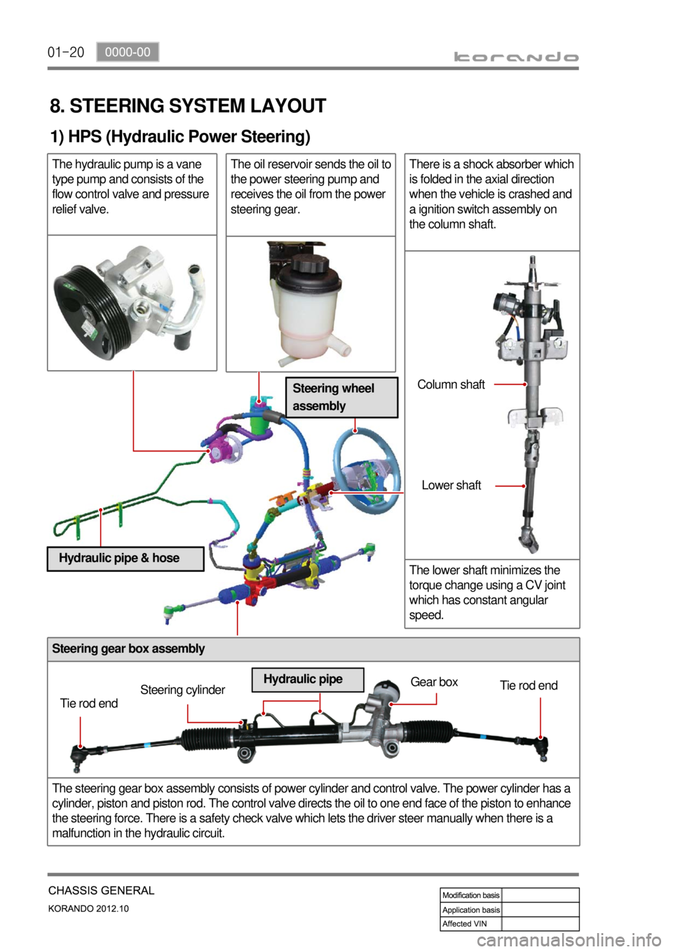
Steering gear box assembly
The steering gear box assembly consists of power cylinder and control valve. The power cylinder has a
cylinder, piston and piston rod. The control valve directs the oil to one end face of the piston to enhance
the steering force. There is a safety check valve which lets the driver steer manually when there is a
malfunction in the hydraulic circuit.
8. STEERING SYSTEM LAYOUT
1) HPS (Hydraulic Power Steering)
The hydraulic pump is a vane
type pump and consists of the
flow control valve and pressure
relief valve.The oil reservoir sends the oil to
the power steering pump and
receives the oil from the power
steering gear.There is a shock absorber which
is folded in the axial direction
when the vehicle is crashed and
a ignition switch assembly on
the column shaft.
The lower shaft minimizes the
torque change using a CV joint
which has constant angular
speed.
Tie rod endSteering cylinderGear box
Tie rod end
Hydraulic pipeColumn shaft
Lower shaft
Steering wheel
assembly
Hydraulic pipe & hose
Page 837 of 1082

02-33680-01
1. GENERAL INFORMATION
Automatic transaxle (M11) ▶
The Model 11 six speed automatic transaxle is
available in two variants: four wheel drive and two
wheel drive.
Six forward speeds
One reverse gear
A toruqe converter with an integral converter
lock-up clutch with slip control capabilities
Electronic shift and pressure controls
A single planetary gear-set
A double planetary gear-set
One hydraulically controlled brake bands
Three multi-plate clutches
One multi plate brake
All hydraulic functions are directed by electronic
solenoids to control: -
-
-
-
-
-
-
-
-
-
Engagement feel
Shift feel
Shift scheduling
Modulated torque converter clutch
applications 1)
2)
3)
4) Inhibitor switch
Oil pan
Torque converter
TCU (located under driver's seat) ▶
TCU is located under the driver's seat and controls
the transaxle operations.
TCU is activated and deactivated by the ignition
voltage, and connected to the transaxle through
pin 26 in connector.
TCU receives and uses the signals from sensors
and switches through CAN bus with analog and
digital types. Driver seat
E-coupling unit
TCU
Passenger
seat
Page 848 of 1082

02-14
5. TRANSAXLE ELECTRONIC CONTROL SYSTEM
1) General Information
The transmission control unit (TCU) and its input/output network control the following transmission
operations:
Shift timing
Line pressure
Clutch pressure (shift feel)
Torque converter clutch -
-
-
-
also uses these signals when determining transaxle operating strategy. Using all of these input signals,
the TCU can determine when the time and conditions are right for a shift, or when to apply or release the
torque converter clutch. It will also determine the pressure needed to optimise shift feel. To accomplish
this, the TCU operates six variable bleed control solenoids and four on/off solenoids to control transaxle
operation.
2) TCU (Transmission Control Unit)
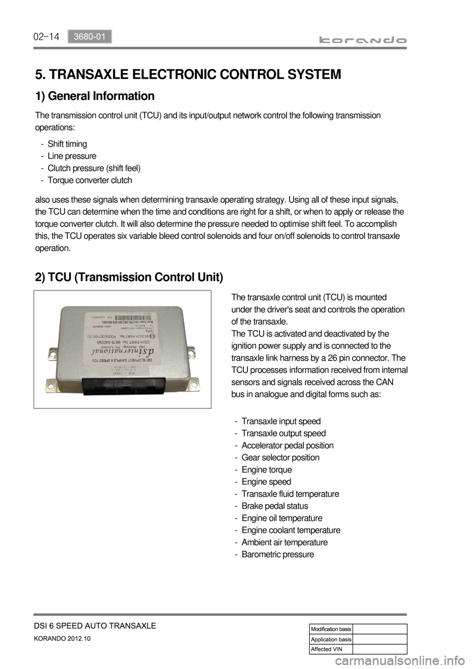
The transaxle control unit (TCU) is mounted
under the driver's seat and controls the operation
of the transaxle.
The TCU is activated and deactivated by the
ignition power supply and is connected to the
transaxle link harness by a 26 pin connector. The
TCU processes information received from internal
sensors and signals received across the CAN
bus in analogue and digital forms such as:
Transaxle input speed
Transaxle output speed
Accelerator pedal position
Gear selector position
Engine torque
Engine speed
Transaxle fluid temperature
Brake pedal status
Engine oil temperature
Engine coolant temperature
Ambient air temperature
Barometric pressure -
-
-
-
-
-
-
-
-
-
-
-
Page 941 of 1082
10-10
4. WARNING LAMPS
1) ABS Warning Lamp
ABS warning lamp module indicates the self diagnosis and malfunction.
ABS warning lamp ON:
When turning the ignition switch to ON position, ABS warning lamp comes on for 3 seconds for self-
diagnosis and goes off if the system is OK (initialization mode).
When the system is defective, the warning lamp comes on.
When the self-diagnosis is performing, the warning lamp comes on.
When the HECU connector is disconnected, the warning lamp comes on.
ABS is not available during lamp ON. In this condition, Only normal brake system without ABS function
is available.
When the communication between warning lamp CAN module in meter cluster, the warning lamp
comes on. 1.
2.
3.
4.
5.
6.
ABS warning lamp
Brake warning lamp
(EBD warning lamp: ABS warning lamp + Brake warning lamp) 1.
2.
Page 942 of 1082

10-114890-00
2) EBD (Electronic Brake-force Distribution) Warning Lamp (Brake
Warning Lamp)
EBD warning lamp when the system performs the self diagnosis and when it detects the malfunction of
EBD system. However, the brake warning lamp comes on regardless of EBD when the parking brake is
applied.
EBD warning lamp ON:
When turning the ignition switch to ON position, ABS warning lamp and the brake warning lamp
comes on for 3 seconds for self diagnosis and goes off if the system is OK (initialization mode).
When applying the parking brake, the brake warning lamp comes on.
When the brake fluid is not sufficient, the brake warning lamp comes on.
When the self-diagnosis is performing, the warning lamp comes on.
When the HECU connector is disconnected, the warning lamp comes on.
When the system is defective, ABS warning lamp and the brake warning lamp come on
simultaneously. 1.
2.
3.
4.
5.
6.
When the solenoid valve is defective
When one or more wheel sensors are defective
When ABS HECU is defective
When the voltage is abnormal
When valve relay is defective a.
b.
c.
d.
e.
When the communication between warning lamp CAN module in meter cluster, the warning lamp
comes on. 7.