Page 848 of 1082

02-14
5. TRANSAXLE ELECTRONIC CONTROL SYSTEM
1) General Information
The transmission control unit (TCU) and its input/output network control the following transmission
operations:
Shift timing
Line pressure
Clutch pressure (shift feel)
Torque converter clutch -
-
-
-
also uses these signals when determining transaxle operating strategy. Using all of these input signals,
the TCU can determine when the time and conditions are right for a shift, or when to apply or release the
torque converter clutch. It will also determine the pressure needed to optimise shift feel. To accomplish
this, the TCU operates six variable bleed control solenoids and four on/off solenoids to control transaxle
operation.
2) TCU (Transmission Control Unit)
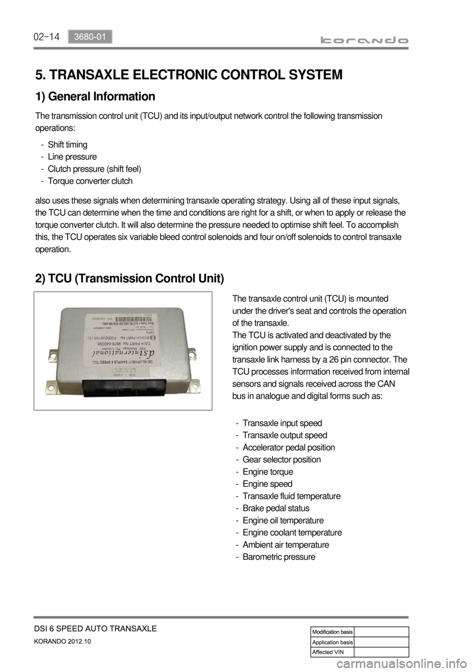
The transaxle control unit (TCU) is mounted
under the driver's seat and controls the operation
of the transaxle.
The TCU is activated and deactivated by the
ignition power supply and is connected to the
transaxle link harness by a 26 pin connector. The
TCU processes information received from internal
sensors and signals received across the CAN
bus in analogue and digital forms such as:
Transaxle input speed
Transaxle output speed
Accelerator pedal position
Gear selector position
Engine torque
Engine speed
Transaxle fluid temperature
Brake pedal status
Engine oil temperature
Engine coolant temperature
Ambient air temperature
Barometric pressure -
-
-
-
-
-
-
-
-
-
-
-
Page 871 of 1082

03-113660-01
1. OVERVIEW
2WD4WD
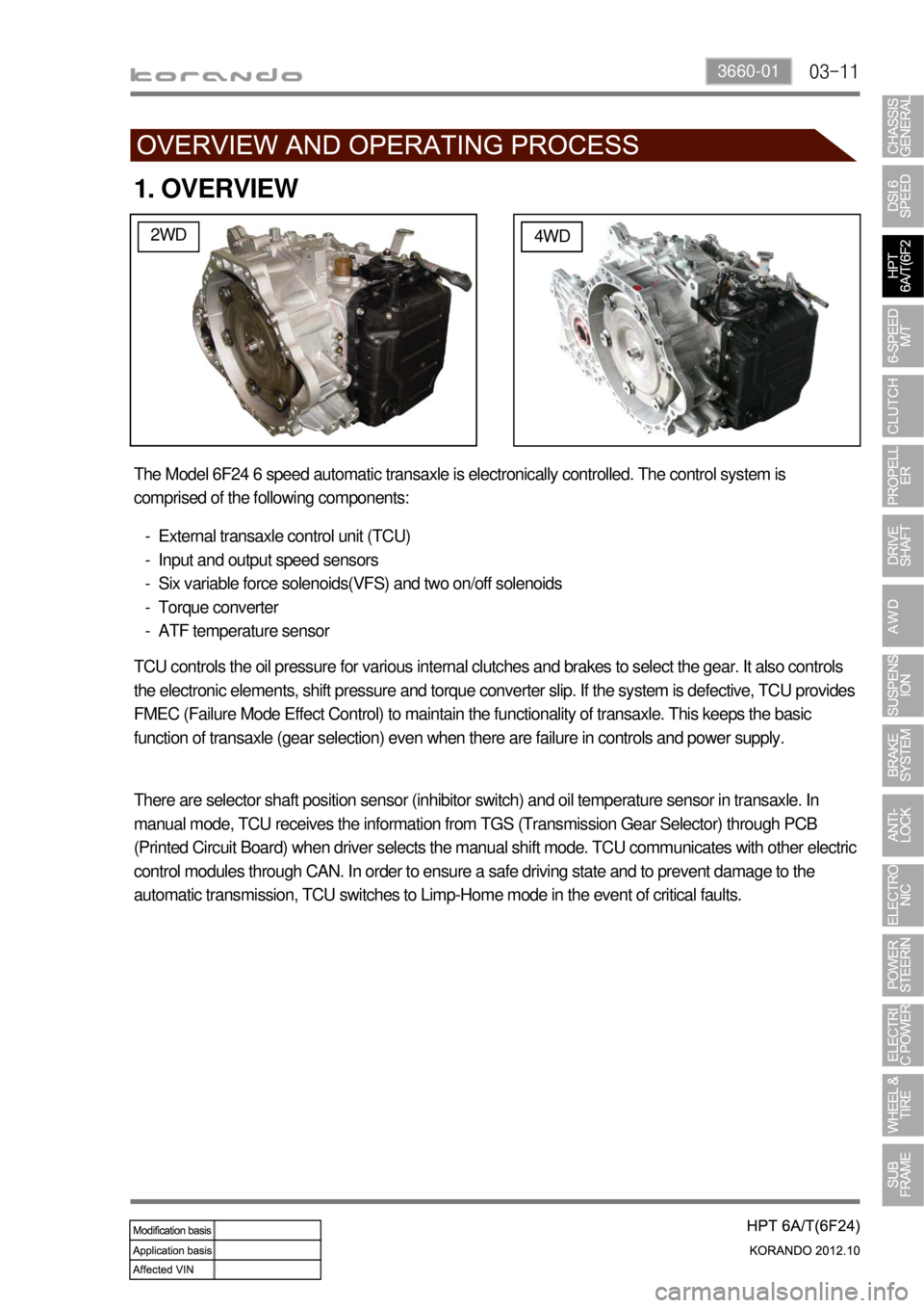
The Model 6F24 6 speed automatic transaxle is electronically controlled. The control system is
comprised of the following components:
External transaxle control unit (TCU)
Input and output speed sensors
Six variable force solenoids(VFS) and two on/off solenoids
Torque converter
ATF temperature sensor -
-
-
-
-
TCU controls the oil pressure for various internal clutches and brakes to select the gear. It also controls
the electronic elements, shift pressure and torque converter slip. If the system is defective, TCU provides
FMEC (Failure Mode Effect Control) to maintain the functionality of transaxle. This keeps the basic
function of transaxle (gear selection) even when there are failure in controls and power supply.
There are selector shaft position sensor (inhibitor switch) and oil temperature sensor in transaxle. In
manual mode, TCU receives the information from TGS (Transmission Gear Selector) through PCB
(Printed Circuit Board) when driver selects the manual shift mode. TCU communicates with other electric
control modules through CAN. In order to ensure a safe driving state and to prevent damage to the
automatic transmission, TCU switches to Limp-Home mode in the event of critical faults.
Page 877 of 1082

03-173660-01
5. TRANSAXLE ELECTRONIC CONTROL SYSTEM
1) General Information
The transmission control unit (TCU) and its input/output network control the following transmission
operations:
Shift timing
Line pressure
Clutch pressure (shift feel)
Torque converter clutch -
-
-
-
also uses these signals when determining transaxle operating strategy. Using all of these input signals,
the TCU can determine when the time and conditions are right for a shift, or when to apply or release the
torque converter clutch. It will also determine the pressure needed to optimise shift feel.
2) TCU (Transmission Control Unit)
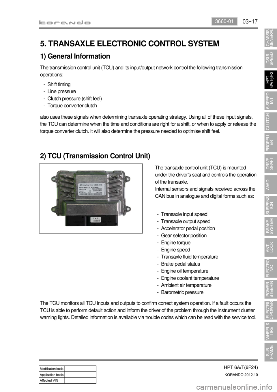
The transaxle control unit (TCU) is mounted
under the driver's seat and controls the operation
of the transaxle.
Internal sensors and signals received across the
CAN bus in analogue and digital forms such as:
Transaxle input speed
Transaxle output speed
Accelerator pedal position
Gear selector position
Engine torque
Engine speed
Transaxle fluid temperature
Brake pedal status
Engine oil temperature
Engine coolant temperature
Ambient air temperature
Barometric pressure -
-
-
-
-
-
-
-
-
-
-
-
The TCU monitors all TCU inputs and outputs to confirm correct system operation. If a fault occurs the
TCU is able to perform default action and inform the driver of the problem through the instrument cluster
warning lights. Detailed information is available via trouble codes which can be read with the service tool.
Page 890 of 1082
03-53190-01
2. TIGHTENING TORQUE
Part name Tightening torque Remark
1. Drive gear mounting bolt of differential carrier 166.6 to 176.4 Nm 10 EA
2. Reverse shaft mounting bolt 74.5 to 89.2 Nm
3. Transmission case mounting bolt 19.6 to 26.5 Nm 22 EA
4. Concentric slave cylinder mounting bolt 11.8 to 14.7 Nm 3 EA
5. Backup lamp switch 29.4 to 34.3 Nm
6. Neutral switch 29.4 to 34.3 Nm
7. Oil filler plug 58.8 to 78.4 Nm
8. Oil drain plug 58.8 to 78.4 Nm
9. Oil plug 58.8 to 78.4 Nm
10. Shift lever mounting nut 42.2 to 53.9 Nm
11. Selector lever mounting nut 42.2 to 53.9 Nm
12. Control shaft assembly mounting bolt 9.8 to 11.8 Nm 7 EA
13. Guide bolt 42.2 to 53.9 Nm
Page 893 of 1082
03-8
1) Characteristics of WM6F1 M/T
Both Forward and Reverse gears use the helical gear and are made of high-strength material.
Drives the clutch with a concentric slave cylinder mounting bolt.
Shifting the transmission gears is performed through the remote control cable.
A pull type clutch is used for Reverse gear shifting.
Features triple/double/single synchronization. -
-
-
-
-
Clutch housing
Transmission case
Input shaft
Concentric slave cylinder
Shift lever
Selector lever
Wiring bracket
Neutral switch
Backup lamp switch
Reverse idle shaft mounting bolt 1.
2.
3.
4.
5.
6.
7.
8.
9.
10.Control guide bolt
Oil filler plug (for servicing)
Oil drain plug
Oil filler plug (for manufacturing)
Air breather
Detent pin (for securing shift fork)
Oil seal (RH)
Oil seal (LH)
Control housing 11.
12.
13.
14.
15.
16.
17.
18.
19.
Page 905 of 1082
04-90000-00
3. DUAL MASS FLYWHEEL (DMF)
The dual mass flywheel (DMF) is of having a mass divided into two halves.
While one mass is connected to the engine crankshaft, which is affected by the mass moment of inertia
of the engine, the other mass is affected by one of the transmission.
The divided dual masses are connected to the coil spring and damping system internally.
The DMF has the following benefits: ▶
Reducing fuel consumption by lowering engine speed
Reducing rattling noise and vehicle vibration in all driving ranges
Reducing synchronization wear
Facilitating gear change
Protecting power train parts by preventing excessive load from being delivered -
-
-
-
-
Primary flywheel
Secondary flywheel
Arc damper spring
Torque limiter
Ring gear 1.
2.
3.
4.
5.