Page 848 of 1082

02-14
5. TRANSAXLE ELECTRONIC CONTROL SYSTEM
1) General Information
The transmission control unit (TCU) and its input/output network control the following transmission
operations:
Shift timing
Line pressure
Clutch pressure (shift feel)
Torque converter clutch -
-
-
-
also uses these signals when determining transaxle operating strategy. Using all of these input signals,
the TCU can determine when the time and conditions are right for a shift, or when to apply or release the
torque converter clutch. It will also determine the pressure needed to optimise shift feel. To accomplish
this, the TCU operates six variable bleed control solenoids and four on/off solenoids to control transaxle
operation.
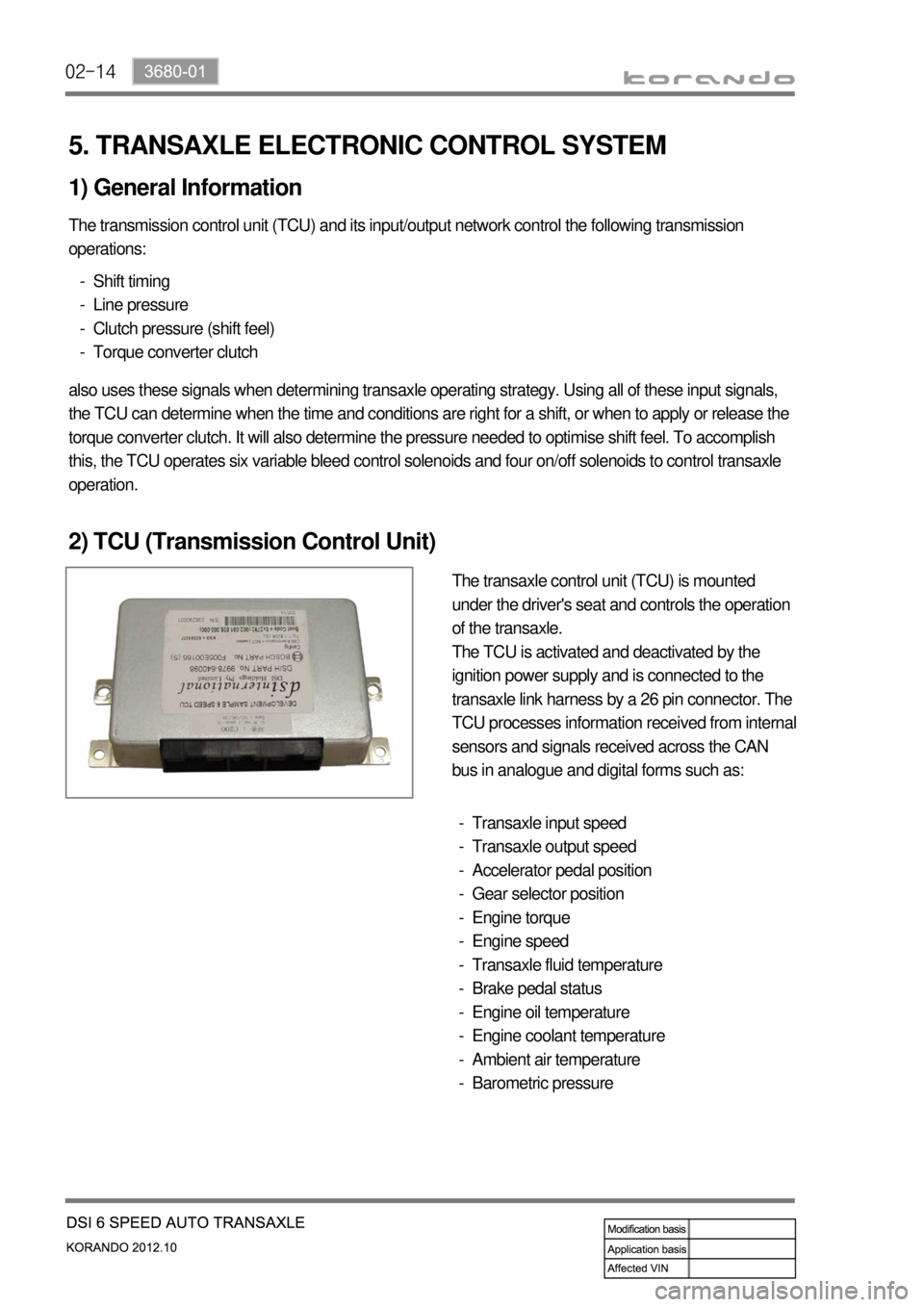
2) TCU (Transmission Control Unit)
The transaxle control unit (TCU) is mounted
under the driver's seat and controls the operation
of the transaxle.
The TCU is activated and deactivated by the
ignition power supply and is connected to the
transaxle link harness by a 26 pin connector. The
TCU processes information received from internal
sensors and signals received across the CAN
bus in analogue and digital forms such as:
Transaxle input speed
Transaxle output speed
Accelerator pedal position
Gear selector position
Engine torque
Engine speed
Transaxle fluid temperature
Brake pedal status
Engine oil temperature
Engine coolant temperature
Ambient air temperature
Barometric pressure -
-
-
-
-
-
-
-
-
-
-
-
Page 864 of 1082
03-4
2. GENERAL INFORMATION
Automatic transaxle (6F24) ▶
The Model 6F24 six speed automatic transaxle is
available in two variants: four wheel drive and two
wheel drive.
Six forward speeds
One reverse gear
A toruqe converter with an integral converter lock-
up clutch with slip control capabilities
Planetary gear-set (3EA)
Clutches (2EA)
Brake (3EA)
O.W.C (1EA)
All hydraulic functions are directed by electronic
solenoids to control: -
-
-
-
-
-
-
-
Engagement feel
Shift feel
Shift scheduling
Modulated torque converter clutch
applications 1)
2)
3)
4) Inhibitor switch
Oil pan
Torque converter
TCU (located under driver's seat) ▶
TCU is located under the driver's seat and controls
the transaxle operations.
TCU receives and uses the signals from sensors
and switches through CAN bus with analog and
digital types. Driver seat
TCU
Passenger
seat
Page 866 of 1082
03-6
3. SPECIFICATIONS
1) Specifications
Type/Weight 6F24 6-speed automatic transaxle /
approx. 86 kg (including ATF)
TORQUE 230 Nm
Overall length / Center length 373.1 mm / 204 mm
Descriptions Specification
Gear ratio 1st gear 4.212
2nd gear 2.637
3rd gear 1.800
4th gear 1.386
5th gear 1.000
6th gear 0.772
Reverse gear 3.385
Shift pattern Variable
Shift range 4 Range (P-R-N-D) + Manual mode
Shift range valve VFS : 6EA
Planetary gear 3EA (Front, Middle, Rear)
Clutch 2EA
Brake 3EA
O.W.C 1EA
Oil Type ATF SP-IV or SP-IV M
Capacity approx. 7.1 L
Change interval Maintenance free. However, under the severe
conditions or commercially used, change the oil at
every 100,000 km (EU: 90,000 km).
Resistance of oil
temperature sensor-20Approx 15.6kΩ
0Approx 5.88kΩ
20Approx 2.51kΩ
100Approx 0.18kΩ
Weight 2WD 87.5kg
4WD 88.5kg
Page 871 of 1082

03-113660-01
1. OVERVIEW
2WD4WD
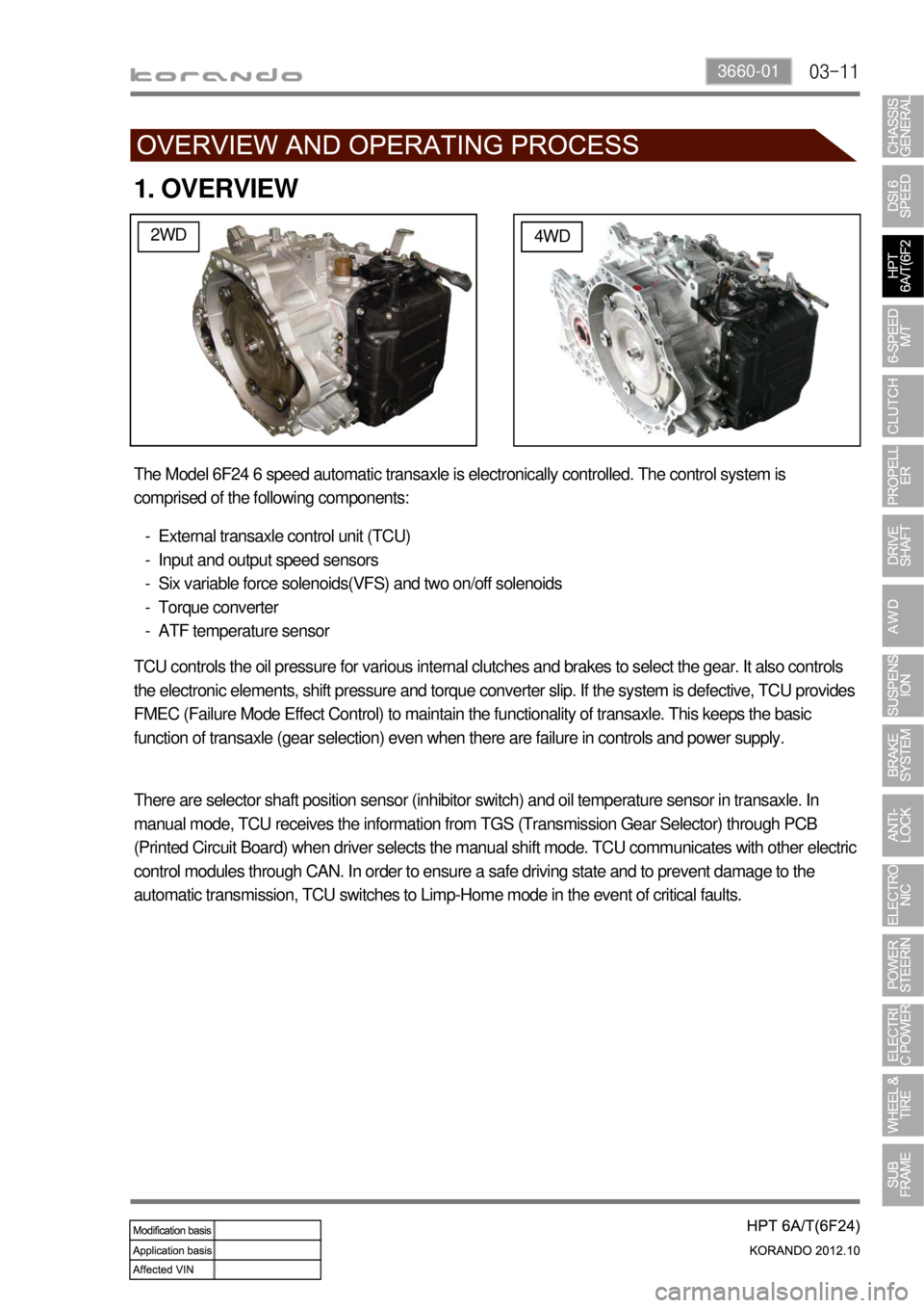
The Model 6F24 6 speed automatic transaxle is electronically controlled. The control system is
comprised of the following components:
External transaxle control unit (TCU)
Input and output speed sensors
Six variable force solenoids(VFS) and two on/off solenoids
Torque converter
ATF temperature sensor -
-
-
-
-
TCU controls the oil pressure for various internal clutches and brakes to select the gear. It also controls
the electronic elements, shift pressure and torque converter slip. If the system is defective, TCU provides
FMEC (Failure Mode Effect Control) to maintain the functionality of transaxle. This keeps the basic
function of transaxle (gear selection) even when there are failure in controls and power supply.
There are selector shaft position sensor (inhibitor switch) and oil temperature sensor in transaxle. In
manual mode, TCU receives the information from TGS (Transmission Gear Selector) through PCB
(Printed Circuit Board) when driver selects the manual shift mode. TCU communicates with other electric
control modules through CAN. In order to ensure a safe driving state and to prevent damage to the
automatic transmission, TCU switches to Limp-Home mode in the event of critical faults.
Page 877 of 1082

03-173660-01
5. TRANSAXLE ELECTRONIC CONTROL SYSTEM
1) General Information
The transmission control unit (TCU) and its input/output network control the following transmission
operations:
Shift timing
Line pressure
Clutch pressure (shift feel)
Torque converter clutch -
-
-
-
also uses these signals when determining transaxle operating strategy. Using all of these input signals,
the TCU can determine when the time and conditions are right for a shift, or when to apply or release the
torque converter clutch. It will also determine the pressure needed to optimise shift feel.
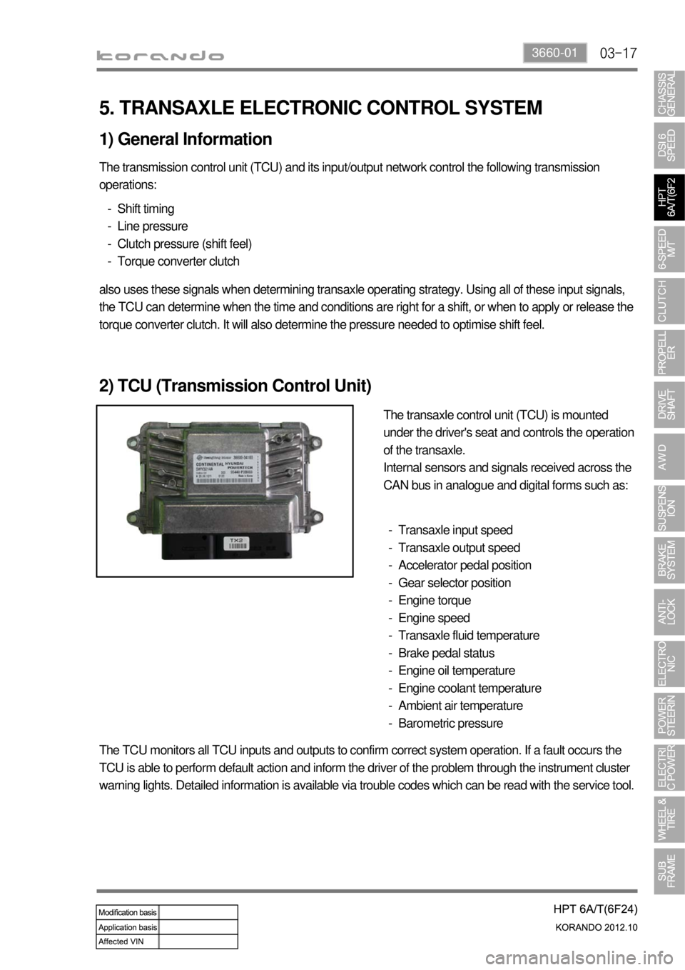
2) TCU (Transmission Control Unit)
The transaxle control unit (TCU) is mounted
under the driver's seat and controls the operation
of the transaxle.
Internal sensors and signals received across the
CAN bus in analogue and digital forms such as:
Transaxle input speed
Transaxle output speed
Accelerator pedal position
Gear selector position
Engine torque
Engine speed
Transaxle fluid temperature
Brake pedal status
Engine oil temperature
Engine coolant temperature
Ambient air temperature
Barometric pressure -
-
-
-
-
-
-
-
-
-
-
-
The TCU monitors all TCU inputs and outputs to confirm correct system operation. If a fault occurs the
TCU is able to perform default action and inform the driver of the problem through the instrument cluster
warning lights. Detailed information is available via trouble codes which can be read with the service tool.
Page 925 of 1082
09-54850-00
F. Front/rear wheel speed sensor
Front/rear-4WD Rear-2WDH. Parking brake
A. Meter cluster-ABS, EBD, ESP
indicator/warning lampB. Master cylinder and
boosterC. HECU
G. Brake pedal
4) Component
ABS warning lamp
ESP indicator
D. Front brake
assembly
E. Rear brake
assembly
Disc
Disc
Parking brake
warning lamp
Caliper
Caliper
Page 926 of 1082

09-6
2. SPECIFICATION (DSL ONLY)
Unit Description Specification
Front brake Type Ventilated disc
Outer diameter of discØ298 mm
Inner diameter of caliper cylinderØ43.0 x 2 mm
Thickness of disc 26 mm (wear limit: 24 mm)
Thickness of brake pad 10.5 mm (wear limit: 2 mm)
Pad wear indicator Mechanical type
Rear brake Type Solid disc
Outer diameter of disc2WD: Ø262 mm, 4WD: Ø284 mm
Thickness of disc 10 mm (wear limit: 8.4 mm)
Thickness of brake pad 10 mm (wear limit: 2 mm)
Pad wear indicator Mechanical type
Brake booster Type Vacuum assist type
Size8” + 9” (Tandem)
Master cylinder Type Tandem (level sensor installed)
Inner diameter of cylinderØ25.4 mm
Brake pedal Maximum operating stroke140 ± 3 mm
Pedal ratio 3.8 : 1
Free play 3 to 10 mm
Parking brake Type Mechanically expanded rear lining
Operating type Hand operated type
Inner diameter of drum2WD: Ø168 mm, 4WD: Ø190 mm
Brake oil Specification DOT 4
Capacity 0.7 to 0.8 liters
Service interval for brake fluid: Change every other year.
Page 937 of 1082
10-6
3. G-sensor (for 4WD)
Located on the floor under
parking brake bracket in center
console.4. Rear wheel speed sensor
(for 2WD)
Located on knuckle. The
appearance is different from that
for 4WD.4. Wheel speed sensor
(for 4WD)
Located on knuckle. The
appearance of front sensor is
same with rear sensor.
2. ABS warning lamp
EBD warning lamp (ABS warning lamp +
Brake warning lamp)1. ABS hydraulic device and control unit
Located under the power steering fluid reservoir and
contains the pressure sensor.
2. COMPONENT