Page 370 of 1082
02-24
3) Oil Pump Chain Tensioner
Layout and Location
Oil pump chain tensioner
Operated by spring in tensioner
Tensioner type: Compensating and absorbing the impact
Static and dynamic force: spring -
-
-
Page 374 of 1082
02-28
2) Operation of DMF
Compensating the irregular operation of engine: The secondary flywheel operates almost evenly so
does not cause gear noises
The mass of the primary flywheel is less than conventional flywheel so the engine irregularity
increases more (less pulsation absorbing effect).
Transaxle protection function: Reduces the torsional vibration to powertrain (transaxle) by reducing
the irregularity of engine. -
-
-
Compression stroke Combustion stroke
Small changes from engine (k):
Damper increases the torque changes to clutchLarge changes from engine (j):
Damper decreases the torque changes to
transaxle by absorbing the impact
Torque change curve of engine and drive shaft
Page 472 of 1082
15-70000-00
Rear oxygen
sensor
2) Components for ECU Input
Coolant temperature
sensorCamshaft position
sensorCrankshaft position
sensor
Front oxygen sensor
Knock sensor
G20DF Engine ECUElectronic throttle
body
Refrigerant pressure sensor
Clutch pedal signal
Blower switch signal
Brake pedal signal
CAN
ABS & ESP
Instrument cluster
TCU -
-
-
Oil pressure
switchOil pressure warning lamp
T-MAP sensor
Page 473 of 1082
15-8
A/C compressorOCV (Oil Control Valve)
3) Components for ECU Output
Start motorInjector
VIS solenoid valve
Purge control solenoid
valve
G20DF Engine ECUIgnition coil
CAN
ABS & ESP unit
BCM
E-coupling unit
EPS
Instrument cluster
SKM
TCU
Diagnostic tool -
-
-
-
-
-
-
-
Cooling fan
module
Page 488 of 1082
15-230000-00
8) CAN Configuration (P-CAN/B-CAN)
(1) CAN Configuration (P-CAN/B-CAN)
Name Function
ECUElectronic Control Unit
TCUTransmission Control Unit
EPSElectronic Power Steering Unit
BCMBody Control Moudule
SKMSmart Key Moudule
CAN system communicates with the system units in vehicle. It consists of P-CAN and B-CAN according
to the communication speed.
P-CAN & B-CAN: SKM, Instrument cluster, BCM, Disgnostic connector
P-CAN: ECU, ABS & ESP, TCU, E-coupling, EPS unit
Terminal resistance: installed on ECU and BCM
Page 572 of 1082

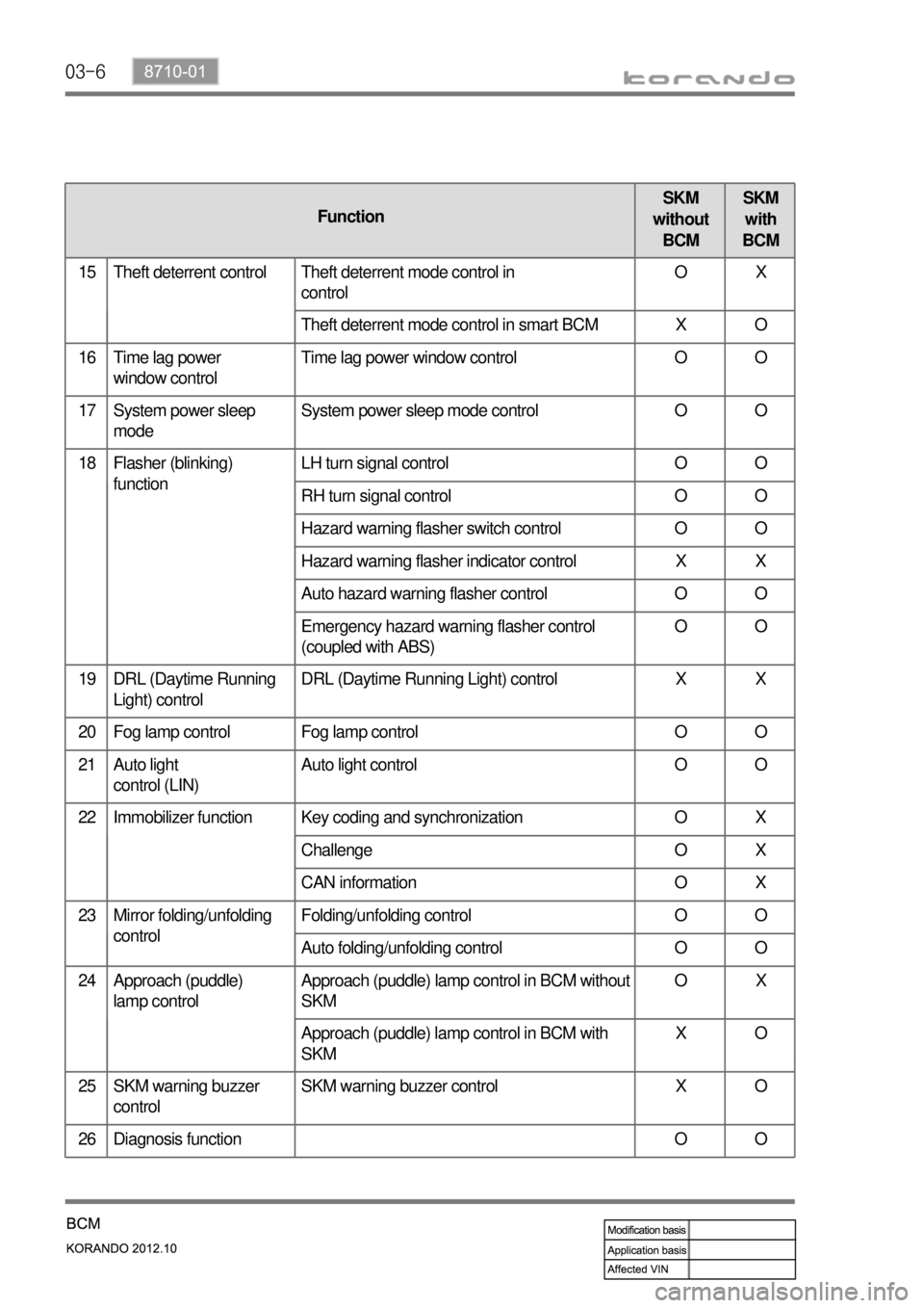
03-6
FunctionSKM
without
BCMSKM
with
BCM
15 Theft deterrent control Theft deterrent mode control in
controlOX
Theft deterrent mode control in smart BCM X O
16 Time lag power
window controlTime lag power window control O O
17 System power sleep
modeSystem power sleep mode control O O
18 Flasher (blinking)
functionLH turn signal control O O
RH turn signal control O O
Hazard warning flasher switch control O O
Hazard warning flasher indicator control X X
Auto hazard warning flasher control O O
Emergency hazard warning flasher control
(coupled with ABS)OO
19 DRL (Daytime Running
Light) controlDRL (Daytime Running Light) control X X
20 Fog lamp control Fog lamp control O O
21 Auto light
control (LIN)Auto light control O O
22 Immobilizer function Key coding and synchronization O X
Challenge O X
CAN information O X
23 Mirror folding/unfolding
controlFolding/unfolding control O O
Auto folding/unfolding control O O
24 Approach (puddle)
lamp control
Approach (puddle) lamp control in BCM without
SKMOX
Approach (puddle) lamp control in BCM with
SKMXO
25 SKM warning buzzer
controlSKM warning buzzer control X O
26 Diagnosis function O O
Page 627 of 1082

03-618710-01
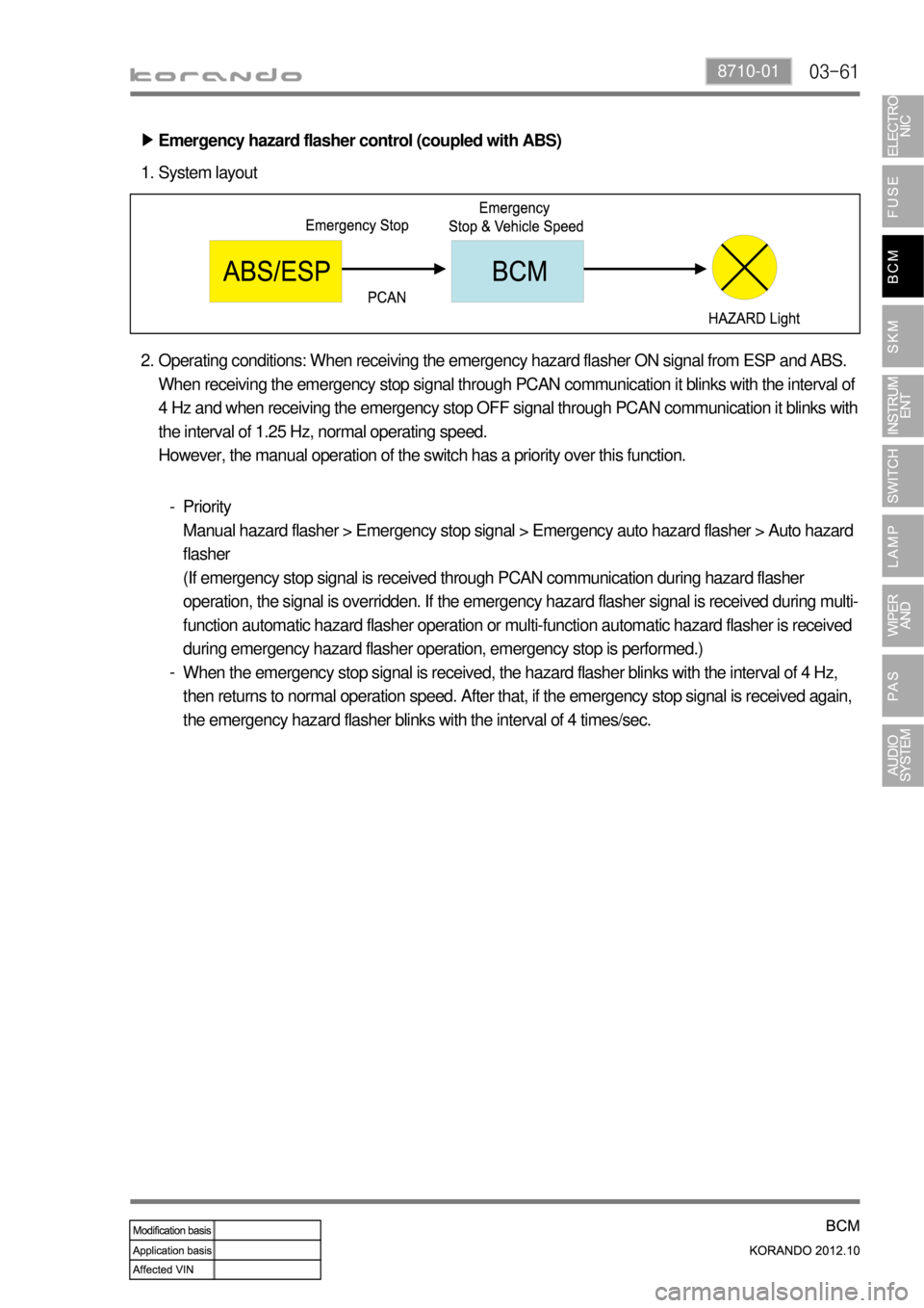
Emergency hazard flasher control (coupled with ABS) ▶
System layout 1.
Operating conditions: When receiving the emergency hazard flasher ON signal from ESP and ABS.
When receiving the emergency stop signal through PCAN communication it blinks with the interval of
4 Hz and when receiving the emergency stop OFF signal through PCAN communication it blinks with
the interval of 1.25 Hz, normal operating speed.
However, the manual operation of the switch has a priority over this function. 2.
Priority
Manual hazard flasher > Emergency stop signal > Emergency auto hazard flasher > Auto hazard
flasher
(If emergency stop signal is received through PCAN communication during hazard flasher
operation, the signal is overridden. If the emergency hazard flasher signal is received during multi-
function automatic hazard flasher operation or multi-function automatic hazard flasher is received
during emergency hazard flasher operation, emergency stop is performed.)
When the emergency stop signal is received, the hazard flasher blinks with the interval of 4 Hz,
then returns to normal operation speed. After that, if the emergency stop signal is received again,
the emergency hazard flasher blinks with the interval of 4 times/sec. -
-
Page 655 of 1082

04-218712-03
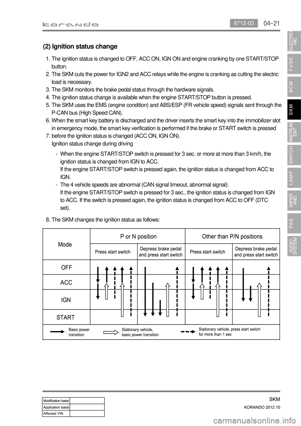
(2) Ignition status change
The ignition status is changed to OFF, ACC ON, IGN ON and engine cranking by one START/STOP
button.
The SKM cuts the power for IGN2 and ACC relays while the engine is cranking as cutting the electric
load is necessary.
The SKM monitors the brake pedal status through the hardware signals.
The ignition status change is available when the engine START/STOP button is pressed.
The SKM uses the EMS (engine condition) and ABS/ESP (FR vehicle speed) signals sent through the
P-CAN bus (High Speed CAN).
When the smart key battery is discharged and the driver inserts the smart key into the immobilizer slot
in emergency mode, the smart key verification is performed if the brake or START switch is pressed
before the ignition status is changed (ACC ON, IGN ON).
Ignition status change during driving 1.
2.
3.
4.
5.
6.
7.
When the engine START/STOP switch is pressed for 3 sec. or more at more than 3 km/h, the
ignition status is changed from IGN to ACC.
If the engine START/STOP switch is pressed again, the ignition status is changed from ACC to
IGN.
The 4 vehicle speeds are abnormal (CAN signal timeout, abnormal signal):
If the engine START/STOP switch is pressed for 3 sec., the ignition status is changed from IGN
to ACC. If the switch is pressed again, the ignition status is changed from ACC to OFF (DTC
set). -
-
The SKM changes the ignition status as follows: 8.