2012 Seat Leon 5D light
[x] Cancel search: lightPage 68 of 289

67
Instruments and warning/control lamps
Trip recorder
Fig. 38 Instrument pan-
el: Odometer and reset
button
The distance covered is displayed in “kilometres” or miles “m”. It is possi-
ble to change the measurement units (kilometres “km”/miles “m”) in the
radio/Easy Connect*. Please refer to the Easy Connect* Instruction Manual
for more details.
Odometer/trip recorder
The odometer shows the total distance covered by the vehicle.
The trip recorder shows the distance that has been travelled since it was
last reset. It is used to measure short trips. The last digit of the trip recorder
indicates distances of 100 metres or one tenths of a mile.
The trip recorder can be set to zero by pressing 0.0/SET
⇒ Fig. 38.
Fault display
If there is a fault in the instrument panel, the letters DEF will appear in the
trip recorder display. Have the fault repaired immediately, as far as is possi-
ble. Fuel level
The display
6 ⇒ Fig. 36 only works when the ignition is switched on. When
the display reaches the reserve mark, the lower diode lights up in red and
the control lamp appears ⇒ page 207. When the fuel level is very low,
the lower diode flashes in red.
The distance to empty fuel level is displayed on the instrument panel 3
⇒ Fig. 36.
The capacity of the fuel tank of your vehicle is given in the Technical data
section ⇒ page 276.
CAUTION
Never run the fuel tank completely dry. An irregular fuel supply could cause
misfiring. In this way the fuel can arrive without burning the exhaust sys-
tem, which could cause the catalytic converter to overheat resulting in dam-
age.
Coolant temperature gauge
For vehicles with no coolant temperature gauge, a control lamp appears for
high coolant temperatures ⇒ page 215. Take into account the ⇒ .
The coolant temperature gauge 2
⇒ Fig. 36 only works when the ignition is
switched on. In order to avoid engine damage, please read the following
notes for the different temperature ranges.
Engine cold
If only the diodes in the lower part of the scale light up, this indicates that
the engine has not yet reached operating temperature. Avoid high revs and
heavy acceleration and do not make the engine work hard.
Safety FirstOperating instructionsPractical TipsTechnical specifications
Page 69 of 289

68Instruments and warning/control lamps
Normal temperature
If in normal operations, the diodes light up until the central zone, it means
that the engine has reached operating temperature. At high outside temper-
atures and when making the engine work hard, the diodes may continue
lighting up and reach the upper zone. This is no cause for concern, provided
the control lamp does not light up on the instrument panel digital dis-
play.
Heat range
When the diodes light up in the upper area of the display and the control
lamp appears on the instrument panel display, the coolant temperature
is excessive ⇒ page 215.
CAUTION
● To ensure a long useful life for the engine, avoid high revs, driving at
high speed and making the engine work hard for approx. the first 15 mi-
nutes when the engine is cold. The phase until the engine is warm also de-
pends on the outside temperature. If necessary, use the engine oil tempera-
ture* as a guide ⇒ page 77
● Additional lights and other accessories in front of the air inlet reduce the
cooling effect of the coolant. At high outside temperatures and high engine
loads, there is a risk of the engine overheating.
● The front spoiler also ensures proper distribution of the cooling air when
the vehicle is moving. If the spoiler is damaged this can reduce the cooling
effect, which could cause the engine to overheat. Seek specialist assis-
tance. Gear-change indicator
This additional indicator function can help to save fuel.
Fig. 39 Instrument pan-
el: Gear-change indicator
(manual gearbox)
To familiarise yourself with the gear-change indicator, we recommend driv-
ing in the normal way to start with. A gear change will be recommended if
the gear you are in is not the most economical choice.
If no gear-change is recommended, you are already in the most economical
gear.
Vehicles with a manual gearbox
The following display symbols ⇒ Fig. 39 mean:
● Change to a higher gear: The suggested gear appears to the right of
the current gear when a higher gear is recommended.
● Change to a lower gear: The suggested gear appears to the left of the
current gear when a lower gear is recommended.
The gear recommendation may occasionally skip a gear (2nd 4th).
Page 71 of 289

70Instruments and warning/control lamps
SymbolMeaning ⇒ See
Use the foot brake!
On the instrument panel display: a)
Fault in the battery.⇒ page 217
a) Colour presentation on instrument panel with colour display.
Yellow symbols
SymbolMeaning ⇒ See
Central warning lamp: additional information
on the instrument panel display–
Front brake pads worn.
⇒ page 183
lights: Fault in the ESC, or disconnection
caused by the system.
flashes: ESC or ASR activated.
ASR manually deactivated.
ABS faulty or does not work.
Rear fog light switched on.⇒ page 106
On the instrument panel display: a)
Driving light totally or partially faulty.⇒ page 252
On the instrument panel display: a)
Fault in the cornering light system.⇒ page 106
SymbolMeaning ⇒ See
Lights up or flashes: Fault in the emission con-
trol system.
⇒ page 190lights: pre-ignition of diesel engine.flashes: Fault in engine management.
Fault in engine management.
On the instrument panel display: a)
Diesel particulate filter blocked.
Lights up or flashes: Fault in the steering sys-
tem.⇒ page 143
Tyre pressure too low, or fault in the tyre pres-
sure monitoring system.⇒ page 175
On the instrument panel display: a)
Level of windscreen washer fluid too low.⇒ page 116
Fuel tank almost empty.⇒ page 207
Flashing on the instrument panel display: a)
Fault in the oil level detection. Control manual-
ly.
⇒ page 211Lit up on the instrument panel display: a)
Engine oil level insufficient.
Fault in airbag system and seat belt tensioners.
⇒ page 30
Front passenger front airbag is off ( PASSENGER
AIRBAG ).
Front passenger front airbag is on ( PASSENGER
AIRBAG ).
Page 72 of 289

71
Instruments and warning/control lamps
SymbolMeaning ⇒ See
Lane Assist is switched on, but not active.⇒ page 168
On the instrument panel display: a)
Fault in the gearbox.⇒ page 162
a) Colour presentation on instrument panel with colour display.
Other control lamps
SymbolMeaning ⇒ See
Left or right turn signal.⇒ page 106
Hazard warning lights on.⇒ page 110
Trailer turn signals⇒ page 194
lights: Press the foot brake!
flashes: The selector lever locking button has
not engaged.⇒ page 154
The vehicle is stopped by engine braking.
lights: Cruise control operating.
⇒ page 164lights: Speed limiter switched on and active.flashes: The speed set by the speed limiter has
been exceeded.
Lane Assist is switched on and active.⇒ page 168
Main beam on or flasher on.⇒ page 106
On the instrument panel display:
Light Assist switched on.
On the instrument panel display:
Immobiliser active.
SymbolMeaning ⇒ See
On the instrument panel display:
Service interval display.⇒ page 65
On the instrument panel display:
Mobile telephone is connected via Bluetooth to
the original telephone device.
⇒ Book-
let Bluetooth
System
On the instrument panel display:
Mobile telephone battery charge meter. Availa-
ble only for pre-installed factory-fitted devices.
On the instrument panel display:
Ice warning. The outside temperature is lower
than +4 °C (+39 °F).⇒ page 64
On the instrument panel display:
Start-Stop system active.
⇒ page 149On the instrument panel display:
Start-Stop system not available.
On the instrument panel display:
Engine running.
WARNING
If the warning lamps and messages are ignored, the vehicle may stall in
traffic, or may cause accidents and severe injuries.
● Never ignore the warning lamps or text messages.
● Stop the vehicle safely as soon as possible.
● Park the vehicle away from the traffic, ensuring that there are no easi-
ly inflammable materials under the vehicle which could come into contact
with the exhaust system (e.g. dry grass, fuel).
● A faulty vehicle represents a risk of accident for the driver and for oth-
er road users. If necessary, switch on the hazard warning lamps and put
out the warning triangle to advise other drivers.
Safety FirstOperating instructionsPractical TipsTechnical specifications
Page 76 of 289

75
Driver information system
Button for the driving assistance systems
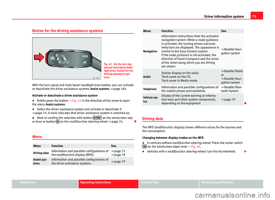
Fig. 42 On the turn sig-
nal and main beam head-
light lever: button for the
driving assistance sys-
tems
With the turn signal and main beam headlight lever button, you can activate
or deactivate the driver assistance systems Assist systems ⇒ page 164.
Activate or deactivate a driver assistance system
● Briefly press the button ⇒ Fig. 42 in the direction of the arrow to open
the menu Assist systems .
● Select the driver assistance system and activate or deactivate it
⇒ page 74. A mark indicates that driver assistance system is switched on.
● Mark or confirm the selection with button
on the windscreen wip-
er lever or button on the multifunction steering wheel
⇒ page 74.
Menu
MenuFunctionSee
Driving dataInformation and possible configurations of
the multifunction display (MFD).⇒ page 75
⇒ page 79
Assist sys-
temsInformation and possible configurations of
the driver assistance systems.⇒ page 79
MenuFunctionSee
Navigation
Information instructions from the activated
navigation system: When a route guidance
is activated, the turning arrows and prox-
imity bars are displayed. The appearance is
similar to the Easy Connect system.
If the route guidance is not activated, the
direction of travel (compass) and the name
of the street along which you are driving
are shown.
⇒ Booklet Navi-
gation system
AudioStation display on the radio.
Track name on the CD.
Track name in Media mode.⇒ Booklet Radio
or
⇒ Booklet Navi-
gation system
TelephoneInformation and possible configurations of
the mobile phone preinstallation.⇒ Booklet Blue-
tooth System
Vehicle sta-
tusDisplay of the current warning or informa-
tion texts and other system components,
depending on the equipment⇒ page 79
Driving data
The MFD (multifunction display) shows different values for the journey and
the consumption.
Changing between display modes on the MFD
● In vehicles without multifunction steering wheel: Press the rocker switch
on the windscreen wiper lever ⇒ Fig. 40.
● Vehicles with a multifunction steering wheel: turn the thumbwheel.
Safety FirstOperating instructionsPractical TipsTechnical specifications
Page 78 of 289

77
Driver information system
DisplaysMenuFunctionOil temperatureUpdated engine oil temperature digital displayCoolant tempera-
ture gaugeDigital display of the current temperature of the liquid
coolant.
Storing a speed for the speed warning
● Select the display Speed warning at --- km/h (--- mph)
● Press the button
on the windscreen wiper lever or the button on the multifunction steering wheel to store the current speed and activate
the warning.
●
If necessary, adjust the desired speed within 5 seconds using the rocker
switch
on the windscreen wiper lever or by turning the thumbwheel on
the multifunction steering wheel. Next, press the button or again
or wait several seconds. The speed is stored and the warning activated.
● To deactivate it press the button
or the button . The stored
speed is deleted.
Assist systems submenu
Assist systems
menuFunction
Lane Assist*Switching the Lane Assist system on or off ⇒ page 170.Tiredness detec-
tion*Switching the tiredness detection on or off (pause recom-
mendation) ⇒ page 173.
Personal convenience settings
When two people use a vehicle, SEAT recommends that each person always
uses their own remote control key. When the ignition is switched off, or the vehicle is locked, the convenience settings are stored and allocated to the
vehicle key
⇒ page 73.
The values of the personalised convenience settings are allocated to the ve-
hicle key in the Easy Connect system via the button
and the function
button Setup ⇒ page 79:
Vehicle settings menu
■ Time
■ Language
■ Units
Convenience settings menu ■ Door unlock (individual opening, Auto Lock)
■ Convenience handling of windows
■ Rear vision mirror adjustment
Light settings menu
■ Coming home and leaving home
■ Footwell light
■ Convenience turn signals
The stored settings are automatically activated, at the latest when the igni-
tion is switched on.
Engine oil temperature display
Vehicles without multifunction steering wheel
– To display the temperature of the engine oil, press the rocker
switch ⇒ Fig. 40 2
until the main menu appears. Enter into
Journey data . With the button 2 move to the oil temperature
gauge.
Safety FirstOperating instructionsPractical TipsTechnical specifications
Page 80 of 289

79
Introduction to the Easy Connect system*
Introduction to the Easy Connect system* System settings (CAR)*Introduction
To select the settings menus, press the Easy Connect button and the
Setup function button.
The actual number of menus available and the name of the various options
in these menus will depend on the vehicle’s electronics and equipment.
Additional information and warnings:
● Driver assistance systems ⇒ page 164
WARNING
Any distraction may lead to an accident, with the risk of injury. Operating
the Easy Connect system while driving could distract you from traffic.
CAR menu (Setup) settings
– Switch the ignition on.
– Switch on the Easy Connect system.
– Press the Easy Connect button
.
– Press the Setup
function button to open the main Vehicle set-
tings menu . Pressing the menu button will always take you to the last menu
used.
Function buttons in the
vehicle’s settings menuPageESC system⇒ page 79Tyres⇒ page 80Driver assistance⇒ page 80Parking and manoeuvring⇒ page 81Vehicle lights⇒ page 81Rear vision mirrors and windscreen wipers⇒ page 82Opening and closing⇒ page 82Multifunction display⇒ page 83Date and time⇒ page 84Units⇒ page 84Service⇒ page 85Factory settings⇒ page 85
Any changes made using the settings menus are automatically saved on
closing those menus.
WARNING
Any distraction may lead to an accident, with the risk of injury. Operating
the Easy Connect system while driving could distract you from traffic.
ESC System menu
–Switch the ignition on.
Safety FirstOperating instructionsPractical TipsTechnical specifications
Page 82 of 289

81
Introduction to the Easy Connect system*
– Press the Driver assistance
function button to open the Driver as-
sistance settings menu.
When the function button check box is activated , the function is active.
Pressing the menu button
will always take you to the last menu used.
MenuSubmenuPossible settingDescription
Driver Assis-
tance settings
Lane Assist (sys-
tem warning you if
you leave the lane)Lane Centring Assist⇒ page 168
Tiredness detec-
tionActivation⇒ page 173
Any changes made using the settings menus are automatically saved on
closing those menus.
WARNING
Any distraction may lead to an accident, with the risk of injury. Operating
the Easy Connect system while driving could distract you from traffic.
Parking and Manoeuvring Settings menu
–Switch the ignition on.
– Switch on the Easy Connect system.
– Press the Easy Connect button
.
– Press the Setup
function button.
– Press the Parking and manoeuvring
button to open the Parking and
manoeuvring settings menu. When the function button check box is activated
, the function is active.
Pressing the menu button
will always take you to the last menu used.
MenuSubmenuPossible settingDescription
Parking and Ma-
noeuvring set-
tingsParkPilot
Automatically acti-
vate, front volume,
front sound settings,
rear volume, rear
sound settings, ad-
just volume.
⇒ page 178
Any changes made using the settings menus are automatically saved on
closing those menus.
WARNING
Any distraction may lead to an accident, with the risk of injury. Operating
the Easy Connect system while driving could distract you from traffic.
Light Settings menu
–Switch the ignition on.
– Switch on the Easy Connect system.
– Press the Easy Connect button
.
– Press the Setup
function button.
– Press the Lights
function button to open the Light settings
menu.
When the function button check box is activated , the function is active.
Safety FirstOperating instructionsPractical TipsTechnical specifications