2012 Seat Exeo display
[x] Cancel search: displayPage 89 of 317

87
Cockpit
Driving time warning
After 2 hours of continuous driving, the display automatically switches over
to the driving time display of 2:00. At the same time the driving time display
starts flashing. This is to remind the driver to take a break.
The driving time warning can be switched off by briefly pressing the func-
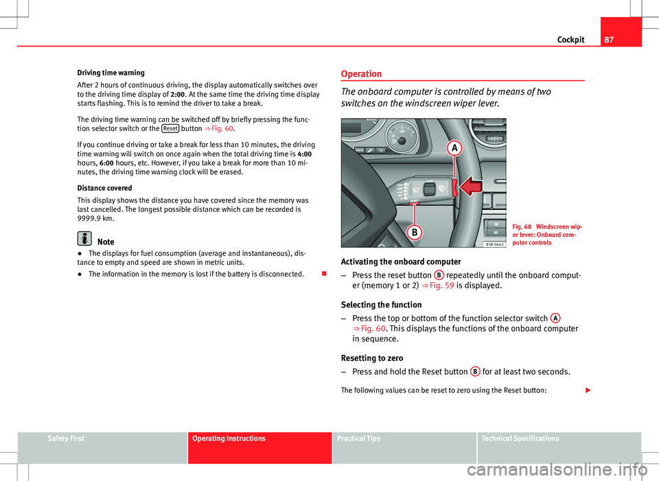
tion selector switch or the Reset
button ⇒ Fig. 60.
If you continue driving or take a break for less than 10 minutes, the driving
time warning will switch on once again when the total driving time is 4:00
hours, 6:00 hours, etc. However, if you take a break for more than 10 mi-
nutes, the driving time warning clock will be erased.
Distance covered
This display shows the distance you have covered since the memory was
last cancelled. The longest possible distance which can be recorded is
9999.9 km.
Note
● The displays for fuel consumption (average and instantaneous), dis-
tance to empty and speed are shown in metric units.
● The information in the memory is lost if the battery is disconnected. Operation
The onboard computer is controlled by means of two
switches on the windscreen wiper lever.
Fig. 60 Windscreen wip-
er lever: Onboard com-
puter controls
Activating the onboard computer
– Press the reset button B
repeatedly until the onboard comput-
er (memory 1 or 2) ⇒ Fig. 59 is displayed.
Selecting the function
– Press the top or bottom of the function selector switch A
⇒ Fig. 60. This displays the functions of the onboard computer
in sequence.
Resetting to zero
– Press and hold the Reset button B
for at least two seconds.
The following values can be reset to zero using the Reset button:
Safety FirstOperating InstructionsPractical TipsTechnical Specifications
Page 90 of 317

88Cockpit
● Journey duration
● Distance covered
● Average fuel consumption
● Average speed
The onboard computer can only be operated when the ignition is switched
on. When the ignition is switched on, the display shows the function that
was last selected.
As well as the figures from the onboard computer (1 or 2), the display can
also show information from the navigation system*. Press the Reset button B
briefly to switch back and forward between these displays.
Note
● If you keep the Reset button pressed for longer than two seconds, it will
reset the currently displayed figure to zero (for instance average fuel con-
sumption).
● Faults detected by the auto-check control will be displayed even if the
display is off.
● The information in the memory is lost if the battery is disconnected.
Page 91 of 317

89
Cockpit
Menu display
Introduction
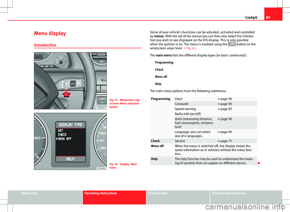
Fig. 61 Windscreen wip-
er lever: Menu selection
button
Fig. 62 Display: Main
menu Some of your vehicle's functions can be adjusted, activated and controlled
by
menus. With the aid of the menus you can then also select the informa-
tion you wish to see displayed on the DIS display. This is only possible
when the ignition is on. The menu is enabled using the Reset
button on the
windscreen wiper lever ⇒ Fig. 61.
The main menu lists the different display types (or basic commands):
Programming
Check
Menu off
Help
The main menu options have the following submenus:
ProgrammingClock⇒ page 90Computer⇒ page 90Speed warning⇒ page 83Radio info (on/off) Units (measuring distance,
fuel consumption, tempera-
ture)⇒ page 90
Language: you can select
one of 6 languages.⇒ page 90
CheckService⇒ page 75Menu offWhen the menu is switched off, the display shows the
same information as in vehicles without the menu func-
tion.
HelpThe help function may be used to understand the mean-
ing of symbols that can appear on different menus.
Safety FirstOperating InstructionsPractical TipsTechnical Specifications
Page 92 of 317

90Cockpit
Controlling the menu
The menu display is called up via the Reset button and the
rocker switch on the windscreen wiper lever. Use these con-
trols to make checks and adjust the settings.
Fig. 63 Windscreen wip-
er lever: Reset button
and rocker switch
Functions of the Reset
B ⇒
Fig. 63 and the rocker switch A:
Activating the menu
– Press the Reset
button until the menu display
⇒ Fig. 62 ap-
pears.
Selecting and setting
– Press the rocker switch to select one of the menus. Press "up"
or "down" on the switch to select the options accordingly.
Entering and confirming
– Press the Reset
button. Use the rocker switch to select the menus and adjust various values. The se-
lected values are highlighted on a red background.
By pressing the
Reset
button, you can confirm the option you have selected
or the value you have set. Selected functions are marked with a tick.
The following symbols are used:
CursorFunction selectedRed background (active
function)
TickSelected
BoxNot selected
Triangle pointing upwardsPrevious page
Triangle pointing down-
wardsNext page
Tyre pressure monitoring* Introduction
The tyre pressure monitoring system constantly checks the
pressure of the tyres.
The system warns the driver in the event of a loss of pressure by means of
symbols and messages in the instrument panel display. The system works
with the help of the ABS sensors in the wheels.
Please bear in mind that the tyre inflation pressure is also influenced by the
temperature of the tyre. Tyre pressure increases about 0.1 bar for each 10 °C
in tyre temperature increase. The tyre heats up while the vehicle is being
Page 93 of 317

91
Cockpit
driven and the tyre pressure will rise accordingly. Therefore, you should only
adjust the tyre pressures when they are cold (i.e. approximately at ambient
temperature).
To ensure that the tyre pressure monitoring system works reliably, you
should check and, if necessary, adjust the tyre pressures at regular intervals
and store the correct pressures (reference values) in the system.
A tyre pressure information label is attached to the inside of the fuel tank
flap.
WARNING
● Never adjust tyre pressure when the tyres are hot. This may damage
or even burst the tyres. Risk of accident!
● An insufficiently inflated tyre flexes a lot more at high speeds and
causes significant heating of the tyre. Under these conditions, the tyre
bead may be released or the tyre may burst. Risk of accident!
For the sake of the environment
Under-inflated tyres lead to increased fuel consumption and tyre wear.
Note
● Responsibility for ensuring that the tyres are correctly inflated remains
with the driver; the system can only provide assistance.
● Pressure can only be adjusted when the tyres are at ambient tempera-
ture. Tyre pressure monitoring display
The tyre pressure should be corrected as soon as possible if
it is too low.
If the symbol appears, the tyre pressure on at least one of the
wheels is too low.
– Stop the vehicle.
– Check the tyre(s).
– Correct the tyre pressure ⇒ page 242.
For more detailed information on the tyre pressure monitoring system,
please refer to ⇒ page 241.
Safety FirstOperating InstructionsPractical TipsTechnical Specifications
Page 94 of 317

92Steering wheel controls
Steering wheel controls
Multifunction steering wheel* Introduction
You can use the multifunction steering wheel to quickly and
easily operate selected functions of the radio, CD, and tele-
phone*.
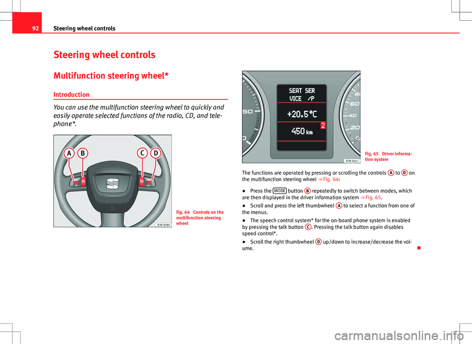
Fig. 64 Controls on the
multifunction steering
wheel
Fig. 65 Driver informa-
tion system
The functions are operated by pressing or scrolling the controls A
to D on
the multifunction steering wheel ⇒ Fig. 64:
● Press the MODE
button
B repeatedly to switch between modes, which
are then displayed in the driver information system ⇒ Fig. 65.
● Scroll and press the left thumbwheel A
to select a function from one of
the menus.
● The speech control system* for the on-board phone system is enabled
by pressing the talk button C
. Pressing the talk button again disables
speed control*.
● Scroll the right thumbwheel D
up/down to increase/decrease the vol-
ume.
Page 101 of 317

99
Unlocking and locking
– Insert the new battery. Make sure that the “+” symbol on the
battery is facing downwards. The correct polarity is indicated on
the cover.
– After inserting the battery, align the cover and key and press
the two parts together.
For the sake of the environment
Used batteries must be disposed of at an appropriate waste facility or
through an authorised service, given that their components can affect the
environment.
Note
● The system must be re-synchronised after each battery replacement to
be able to lock and unlock the vehicle using the remote control
⇒ page 107.
● The new battery must be of the same type as the original.
Electronic immobiliser
The electronic immobiliser is designed to prevent unauthor-
ised persons from starting up the vehicle.
There is an electronic chip inside the key which automatically deactivates
the immobiliser when the key is inserted into the ignition lock. The electron-
ic immobiliser is enabled automatically when the ignition key is removed
from the ignition lock after coming to a stop.
If an uncoded key is used, the message SAFE will appear in the trip recorder
display.
Note
● The engine can only be started using an original SEAT key with the cor-
rect code.
● It may not be possible to start the engine with the key if there is another
ignition key from a different make of vehicle on the same key tab.
Central locking Description
The central locking system enables you to lock and unlock
all the doors, the rear lid and the tank flap together.The central locking system on your vehicle locks and unlocks all the doors
and the tank flap simultaneously. The rear lid is unlocked when the vehicle
is opened. However, the handle must be used to open it. The vehicle can be
locked and unlocked using the remote control ⇒ page 105 or by turning the
key in the lock in the driver door.
The windows can also be centrally opened or closed using the central lock-
ing system ⇒ page 111. The sunroof* can be closed but not opened using
the central locking system.
The central locking system is combined with an anti-theft security system.
If the vehicle is locked with the key from the outside, the interior opening
levers stop working, which prevents unauthorised persons from entering
the vehicle.
Should the central locking system fail to work, you can activate all the locks
individually.
Safety FirstOperating InstructionsPractical TipsTechnical Specifications
Page 121 of 317

119
Lights and visibility
Instrument lighting
The brightness of the instrument lighting, displays and cen-
tre console lighting can be varied as required.
Fig. 85 Instrument panel
lighting
– Press the +
button to increase the brightness.
– Press the -
button to reduce the brightness.
With the ignition switched on
The lighting of the digital displays will adjust automatically, depending on
the ambient light.
With the vehicle's lights switched on
When the vehicle's lights are switched on, the brightness of the instrument
lighting, displays and centre console lighting can be varied by pressing the +
and - buttons. Headlight range control
When the dipped beam headlights are switched on, the
range of the headlights can be adjusted to suit the load of
the vehicle.
Fig. 86 Headlight range
control
– Briefly press the knob ⇒ Fig. 86 to release it from its set posi-
tion.
– Turn the knob to the required setting.
– Press the knob in again to prevent the setting from being
changed unintentionally.
Settings
The settings roughly correspond to the following load conditions: Two front occupants, luggage compartment empty
All seats occupied, luggage compartment empty
O
1
Safety FirstOperating InstructionsPractical TipsTechnical Specifications