2012 Seat Altea Freetrack set clock
[x] Cancel search: set clockPage 61 of 297

59
Cockpit
Needle in warning zone C
The warning lamp* ⇒ fig. 49 2 will light up if the needle is in the warning
zone. The following warning message appears on the instrument panel dis-
play 1)
. Stop the vehicle and switch off the engine. Check the coolant level
⇒ page 226 ⇒
.
Even if the coolant level is correct do not continue driving. You should seek
specialised technical assistance.
WARNING
When working in the engine compartment, always observe the safety
warnings ⇒ page 219.
CAUTION
Accessories in front of the air inlet reduce the cooling effect of the coolant.
At high outside temperatures and high engine loads, there is a risk of the
engine overheating.
Rev counter
The rev counter displays the engine speed in revolutions per
minute. The start of the red zone ⇒ fig. 34 4
indicates the maximum engine speed
operating at service temperature. However, it is advisable to change up a in-
to a higher gear, move the selector lever to D or lift your foot off the acceler-
ator before the needle reaches the red zone.
CAUTION
The rev counter needle must never enter the red zone on the scale. Risk of
engine damage.
For the sake of the environment
Changing up into higher gears sooner, following the recommended gear in-
dications ⇒ fig. 39 will help you to reduce fuel consumption, emissions and
also engine noise.
Speedometer
The speedometer is equipped with a digital odometer and a trip recorder, in
addition to a service intervals display.
During the running-in period, the instructions shown on ⇒ page 195
should be followed.
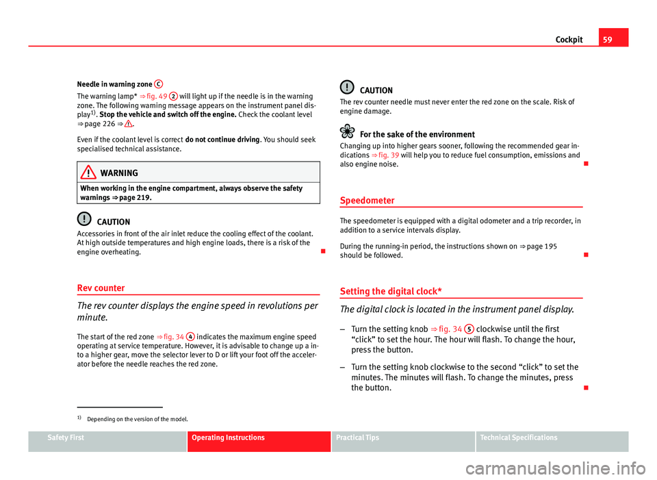
Setting the digital clock*
The digital clock is located in the instrument panel display.
– Turn the setting knob ⇒ fig. 34 5
clockwise until the first
“click” to set the hour. The hour will flash. To change the hour,
press the button.
– Turn the setting knob clockwise to the second “click” to set the
minutes. The minutes will flash. To change the minutes, press
the button.
1)
Depending on the version of the model.
Safety FirstOperating InstructionsPractical TipsTechnical Specifications
Page 62 of 297

60Cockpit
Digital instrument panel display
Display (without warning or information texts)
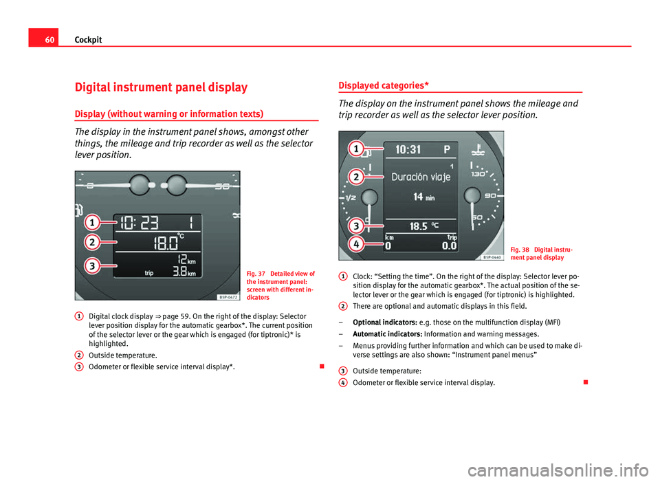
The display in the instrument panel shows, amongst other
things, the mileage and trip recorder as well as the selector
lever position.
Fig. 37 Detailed view of
the instrument panel:
screen with different in-
dicators
Digital clock display ⇒ page 59. On the right of the display: Selector
lever position display for the automatic gearbox*. The current position
of the selector lever or the gear which is engaged (for tiptronic)* is
highlighted.
Outside temperature.
Odometer or flexible service interval display*.
1
23
Displayed categories*
The display on the instrument panel shows the mileage and
trip recorder as well as the selector lever position.
Fig. 38 Digital instru-
ment panel display
Clock: “Setting the time”. On the right of the display: Selector lever po-
sition display for the automatic gearbox*. The actual position of the se-
lector lever or the gear which is engaged (for tiptronic) is highlighted.
There are optional and automatic displays in this field.
Optional indicators: e.g. those on the multifunction display (MFI)
Automatic indicators: Information and warning messages.
Menus providing further information and which can be used to make di-
verse settings are also shown: “Instrument panel menus”
Outside temperature:
Odometer or flexible service interval display.
1
2
–
–
–
3
4
Page 63 of 297

61
Cockpit
Recommended gear display*
This display helps to save fuel.
Fig. 39 Gear display
Use the gear display to save fuel. If you are driving in the correct gear, a dot
will be shown next to the gear display. If you are not in the correct gear, an
arrow will appear next to the gear display indicating whether you should
change up or down.
Note
The gear change indication should not be taken into account the accelera-
tion is required (for example when overtaking).
Odometer or flexible service interval display
Odometer
The left-hand counter in the display registers the total amount of distance
covered by the vehicle. The right-hand counter registers the short journeys. The last digit indicates
steps of 100 metres. The trip recorder counter may be reset by holding
down the reset button for a few seconds.
Service interval display
Vehicles with
Service intervals dependent on time/distance travelled al-
ready have certain service intervals set. The intervals are calculated individ-
ually in vehicles with LongLife service.
The service interval display only indicates the dates of services that include
engine oil change. The dates of all other services, such as Inspection Serv-
ice or brake fluid change, appear in the sticker on the door pillar or in the
Maintenance Programme.
A Service pre-warning will appear in the odometer if a service is due soon. A
“spanner” symbol appears and the display “km” with the distance that can
be driven until the next service appointment is due. The display will change
after approximately 10 seconds. A “clock symbol” appears and the number
of days until the service appointment should be carried out. The following
message is shown in the instrument panel display*: Service in
[XXXX]
kmor
[XXXX]
days
The service message will disappear approximately 20 seconds after the ig-
nition is switched on or the engine is running. The normal display can be
resumed by briefly pressing the reset button on the trip counter or by press-
ing the OK
button on the steering wheel controls.
With the ignition on, you can check the current service message at any mo-
ment in the Vehicle status menu or turning the reset button to access the
service display.
An overdue service is indicated by a minus sign in front of the mileage or
day information.
Safety FirstOperating InstructionsPractical TipsTechnical Specifications
Page 75 of 297

73
Cockpit
Vehicle status menu
This menu shows warning or information texts
Open Vehicle Condition menu
– Select the option Vehicle status from the main menu: “Main
menu” and press button OK
on the windscreen wiper lever
A⇒ fig. 46. or
– Press button
or on the multifunction steering wheel*
⇒ fig. 45 until the Vehicle Status menu is displayed.
Priority 2 warning messages and information texts: “Information and warn-
ing messages on the screen” will automatically disappear from the screen
after a time and will be stored in the Vehicle status menu.
The warning and information texts may be viewed in this menu. If there is
no warning or information message, the option Vehicle status is not dis-
played. If there are several messages, each one is shown for a few seconds.
Example of menu use ⇒ page 67
Note
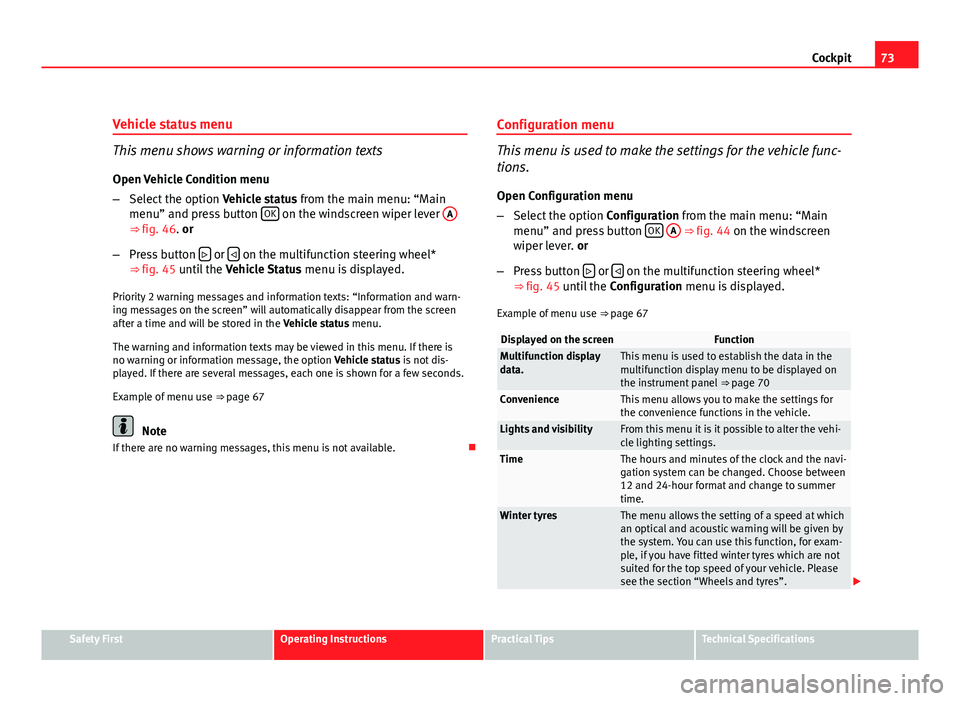
If there are no warning messages, this menu is not available. Configuration menu
This menu is used to make the settings for the vehicle func-
tions.
Open Configuration menu
– Select the option Configuration from the main menu: “Main
menu” and press button OK
A ⇒ fig. 44 on the windscreen
wiper lever. or
– Press button
or on the multifunction steering wheel*
⇒ fig. 45 until the Configuration menu is displayed.
Example of menu use ⇒ page 67
Displayed on the screenFunctionMultifunction display
data.This menu is used to establish the data in the
multifunction display menu to be displayed on
the instrument panel ⇒ page 70
ConvenienceThis menu allows you to make the settings for
the convenience functions in the vehicle.
Lights and visibilityFrom this menu it is it possible to alter the vehi-
cle lighting settings.
TimeThe hours and minutes of the clock and the navi-
gation system can be changed. Choose between
12 and 24-hour format and change to summer
time.
Winter tyresThe menu allows the setting of a speed at which
an optical and acoustic warning will be given by
the system. You can use this function, for exam-
ple, if you have fitted winter tyres which are not
suited for the top speed of your vehicle. Please
see the section “Wheels and tyres”.
Safety FirstOperating InstructionsPractical TipsTechnical Specifications
Page 159 of 297

157
Air conditioning
Note
Please observe the general notes ⇒ page 164.
Heating and cooling the interior
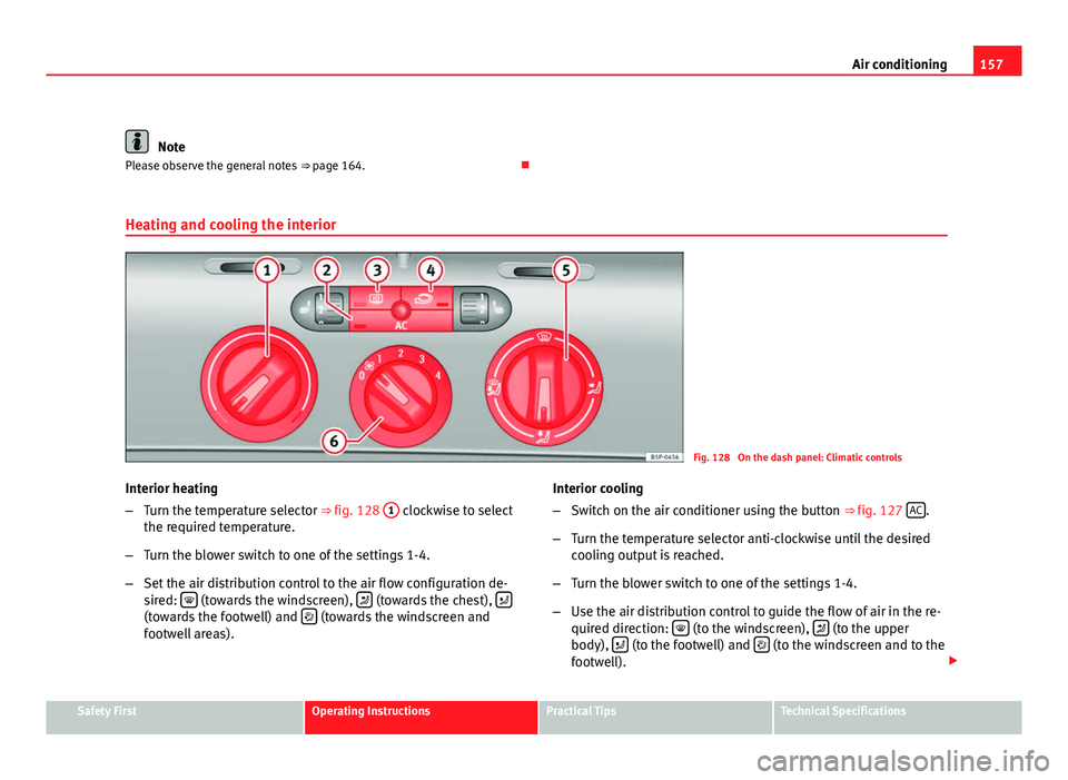
Fig. 128 On the dash panel: Climatic controls
Interior heating
– Turn the temperature selector ⇒ fig. 128 1
clockwise to select
the required temperature.
– Turn the blower switch to one of the settings 1-4.
– Set the air distribution control to the air flow configuration de-
sired:
(towards the windscreen), (towards the chest), (towards the footwell) and (towards the windscreen and
footwell areas). Interior cooling
–
Switch on the air conditioner using the button ⇒ fig. 127 AC
.
– Turn the temperature selector anti-clockwise until the desired
cooling output is reached.
– Turn the blower switch to one of the settings 1-4.
– Use the air distribution control to guide the flow of air in the re-
quired direction:
(to the windscreen), (to the upper
body), (to the footwell) and (to the windscreen and to the
footwell).
Safety FirstOperating InstructionsPractical TipsTechnical Specifications
Page 275 of 297

273
If and when
Trailer eyes
Fig. 199 The front right
section of the vehicle:
Fitting the front towing
eye
Fig. 200 Fitting the tow-
ing eye to the rear of the
vehicle
Fitting the towing eye
– Take the towing ring from the on-board tool set. –
Remove the front cover by pressing down on its left-hand side.
– Remove the rear cover by pressing down on the right hand side.
– Screw the towing eye as shown by the arrow anti-clockwise to
the limit position in the front ⇒ fig. 199 or rear ⇒ fig. 200 threa-
ded hole.
Safety FirstOperating InstructionsPractical TipsTechnical Specifications