Page 105 of 510

13B-105
AFTER REPAIRDeal with any other faults. Clear the fault memory.
Switch off the ignition until the end of the power-latch phase, and carry out a road test
followed by a check with the diagnostic tool.
V12 MR-372-J84-13B300$072.mif
DIESEL INJECTION
Fault finding – Interpretation of faults13B
EDC16CP33
Program No.: C4
Vdiag No.: 04, 08, 18, 1C,
20, 24, 26, 28, 34, 38, 44,
4C, 54, 58, 5C, 60, 62, 74
DF046
CONTINUED
2.DEFNOTESNone.
Using a voltmeter, take a reading of the battery voltage at its terminals.
Compare this value with the value displayed by the diagnostic tool PR074 Battery voltage.
If there is no difference (less than 1 V):
– Recharge and test the battery. If it is faulty, replace it.
– Check the charging circuit: Technical Note 6014A Checking the charging circuit.
If there is a difference (greater than 1 V):
– Check the tightness and the condition of the battery terminals.
Using the appropriate wiring diagram:
–Check the continuity and absence of interference resistance on the following connection:
•3FB between components 120 and 983 or 1337.
Check the conformity of the earths on connections NT of component 120.
If the connection or connections are faulty and if there is a repair method (see Technical Note 6015A, Electrical
wiring repair, Wiring: Precautions for repair), repair the wiring, otherwise replace the wiring.
3.DEF
NOTESOnly deal with this fault when it is present.
Switch off the ignition, wait for the diagnostic tool message (maximum wait 8 min): Loss of dialogue with the
computer: EDC16 CP33, check the tool connection and the computer supply voltage then switch on the
ignition again and check whether the fault is still present.
If the fault is still present, contact the Techline.
Page 106 of 510

13B-106
AFTER REPAIRDeal with any other faults. Clear the fault memory.
Switch off the ignition until the end of the power-latch phase, and carry out a road test
followed by a check with the diagnostic tool.
V12 MR-372-J84-13B300$072.mif
DIESEL INJECTION
Fault finding – Interpretation of faults13B
EDC16CP33
Program No.: C4
Vdiag No.: 04, 08, 18, 1C,
20, 24, 26, 28, 34, 38, 44,
4C, 54, 58, 5C, 60, 62, 74
DF047
PRESENT
OR
STOREDCOMPUTER SUPPLY VOLTAGE
1.DEF: Voltage outside permitted range of values
NOTESConditions for applying the fault finding procedure to a stored fault:
If the fault is declared present after:
– starting the engine,
– a road test.
Special notes:
Use bornier Elé.1681 for any operations on the injection computer connectors.
Use the Wiring Diagram Technical Note, Laguna II ph2, Vel Satis ph2, Espace IV
ph2, Mégane II ph2, Scénic II ph2.
Check the tightness and the condition of the battery terminals.
Using the appropriate wiring diagram:
–Check the continuity and absence of interference resistance on the following connection:
•3FB between components 120 and 983 or 1337.
Check the conformity of the earths on connections NT of component 120.
If the connection or connections are faulty and if there is a repair method (see Technical Note 6015A, Electrical
wiring repair, Wiring: Precautions for repair), repair the wiring, otherwise replace the wiring.
EDC16CP33_V18_DF047 / EDC16CP33_V1C_DF047 / EDC16CP33_V54_DF047 / EDC16CP33_V20_DF047 / EDC16CP33_V58_DF047 /
EDC16CP33_V5C_DF047 / EDC16CP33_V24_DF047 / EDC16CP33_V04_DF047 / EDC16CP33_V08_DF047 / EDC16CP33_V44_DF047 /
EDC16CP33_V4C_DF047 / EDC16CP33_V34_DF047 / EDC16CP33_V38_DF047 / EDC16CP33_V74_DF047 / EDC16CP33_V28_DF047 /
EDC16CP33_V62_DF047/ EDC16CP33_V26_DF047 / EDC16CP33_V60_DF047
Page 447 of 510

13B-447V12 MR-372-J84-13B300$150.mif
DIESEL INJECTION
Fault finding – Interpretation of commands13B
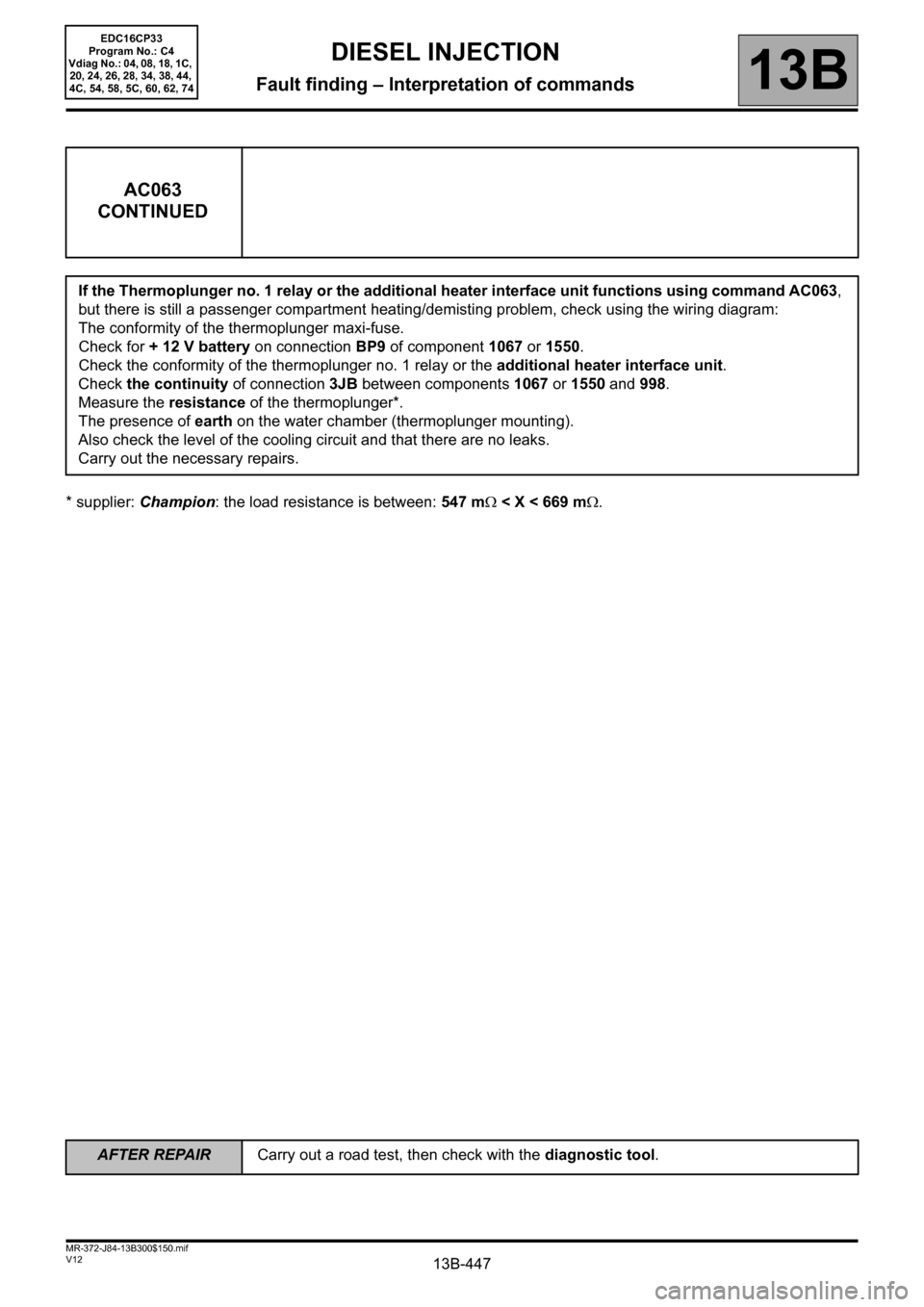
* supplier: Champion: the load resistance is between: 547 mΩ < X < 669 mΩ.
AC063
CONTINUED
If the Thermoplunger no. 1 relay or the additional heater interface unit functions using command AC063,
but there is still a passenger compartment heating/demisting problem, check using the wiring diagram:
The conformity of the thermoplunger maxi-fuse.
Check for + 12 V battery on connection BP9 of component 1067 or 1550.
Check the conformity of the thermoplunger no. 1 relay or the additional heater interface unit.
Check the continuity of connection 3JB between components 1067 or 1550 and 998.
Measure the resistance of the thermoplunger*.
The presence of earth on the water chamber (thermoplunger mounting).
Also check the level of the cooling circuit and that there are no leaks.
Carry out the necessary repairs.
EDC16CP33
Program No.: C4
Vdiag No.: 04, 08, 18, 1C,
20, 24, 26, 28, 34, 38, 44,
4C, 54, 58, 5C, 60, 62, 74
AFTER REPAIRCarry out a road test, then check with the diagnostic tool.