2012 RENAULT SCENIC geometry
[x] Cancel search: geometryPage 220 of 510

13B-220
AFTER REPAIRDeal with any other faults. Clear the fault memory.
Switch off the ignition until the end of the power-latch phase, and carry out a road test
followed by a check with the diagnostic tool.
V12 MR-372-J84-13B300$074.mif
DIESEL INJECTION
Fault finding – Interpretation of faults13B
DF569
CONTINUED 2
Check for continuity and absence of interference resistance of the following connections:
●3LQ between components 120 and 1071,
●3LP between components 120 and 1071,
●3LN between components 120 and 1071.
If the connection or connections are faulty and there is a repair procedure (see Technical Note 6015A, Electrical
wiring repair, Wiring: Precautions for repair), repair the wiring, otherwise replace it.
Test the high pressure fuel circuit:
Apply scenario SC035 High pressure fuel circuit fault finding.
To interpret the result, apply the interpretation of command SC035 (see Interpretation of commands).
With the engine stopped and ignition on, view parameters PR035 Atmospheric pressure and PR041
Turbocharging pressure.
If there is a difference of > 100 mbar, check that the atmospheric pressure reading is consistent (by comparison
with another vehicle for example).
If atmospheric pressure is consistent, replace the turbocharging sensor.
If not, contact the Techline.
Use the Monitool application: MT001 Turbocharging function to check the entire air line (only for Vdiag 04 and
44).
Apply Test 4 Turbocharged air inlet circuit check.
Run Test 7 Variable geometry turbocharger control.
Run Test 8 Turbocharger rotating part.
If the fault is still present, refer to the interpretation of parameter PR041 Turbocharging pressure.
If the fault is still present, contact the Techline.
EDC16CP33
Program No.: C4
Vdiag No.: 04, 08, 18, 1C,
20, 24, 26, 28, 34, 38, 44,
4C, 54, 58, 5C, 60, 62, 74
Page 260 of 510

13B-260
AFTER REPAIRDeal with any other faults. Clear the fault memory.
Switch off the ignition until the end of the power-latch phase, and carry out a road test
followed by a check with the diagnostic tool.
V12 MR-372-J84-13B300$074.mif
DIESEL INJECTION
Fault finding – Interpretation of faults13B
DF1188
CONTINUED
Apply Test 4 Turbocharged air inlet circuit check.
Apply Test 7 Variable geometry turbocharger control.
Apply Test 8 Turbocharger rotating part.
Run Test 11 Temperature upstream of turbine too low.
Check the take-off point of the turbine upstream pressure sensor
If the fault is still present, contact the Techline.
EDC16CP33
Program No.: C4
Vdiag No.: 04, 08, 20, 24,
34, 38, 44, 4C, 60, 62, 74
Page 440 of 510
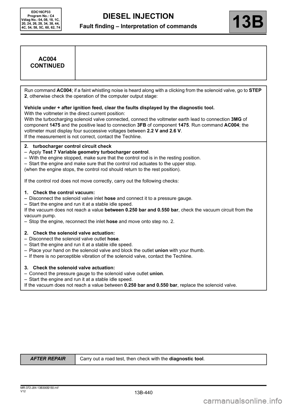
13B-440V12 MR-372-J84-13B300$150.mif
DIESEL INJECTION
Fault finding – Interpretation of commands13B
AC004
CONTINUED
Run command AC004; if a faint whistling noise is heard along with a clicking from the solenoid valve, go to STEP
2, otherwise check the operation of the computer output stage:
Vehicle under + after ignition feed, clear the faults displayed by the diagnostic tool.
With the voltmeter in the direct current position:
With the turbocharging solenoid valve connected, connect the voltmeter earth lead to connection 3MG of
component 1475 and the positive lead to connection 3FB of component 1475. Run command AC004; the
voltmeter must display four successive voltages between 2.2 V and 2.6 V.
If the measurement is not correct, contact the Techline.
2. turbocharger control circuit check
–Apply Test 7 Variable geometry turbocharger control.
– With the engine stopped, make sure that the control rod is in the resting position.
– Start the engine and make sure that the control rod actuates to the upper stop.
(when the engine stops, the control rod should return to the rest position).
If the control rod does not move correctly, carry out the following checks:
1. Check the control vacuum:
– Disconnect the solenoid valve inlet hose and connect it to a pressure gauge.
– Start the engine and run it at a stable idle speed.
If the vacuum does not reach a value between 0.250 bar and 0.550 bar, check the vacuum circuit from the
vacuum pump.
– Stop the engine, reconnect the inlet hose and move onto step no. 2.
2. Check the solenoid valve actuation:
– Disconnect the solenoid valve outlet hose.
– Start the engine and run it at a stable idle speed.
– Place your hand on the solenoid valve and block the outlet union with your thumb.
– If there is no perceptible vibration of the solenoid valve, contact the Techline.
3. Check the solenoid valve actuation:
– Connect the pressure gauge to the solenoid valve outlet union.
– Start the engine and run it at a stable idle speed.
If the vacuum does not reach a value between 0.250 bar and 0.550 bar, replace the solenoid valve.
EDC16CP33
Program No.: C4
Vdiag No.: 04, 08, 18, 1C,
20, 24, 26, 28, 34, 38, 44,
4C, 54, 58, 5C, 60, 62, 74
AFTER REPAIRCarry out a road test, then check with the diagnostic tool.
Page 462 of 510

13B-462V12 MR-372-J84-13B300$150.mif
DIESEL INJECTION
Fault finding – Interpretation of commands13B
MT001
CONTINUED 3
Fault finding procedure Monitool no. 1:
– Check the fitting of the air flowmeter (direction of fitting to be observed).
– Check the tightness of the different air flowmeter clips.
– Check the + 5 V supply of connection 3KJ of component 799.
If the connection is faulty and there is a repair procedure (see Technical Note 6015A, Electrical wiring repair,
Wiring: Precautions for repair), repair the wiring, otherwise replace it.
– Check that there are no air leaks between the air flowmeter and the turbocharger.
– Run Test 5 Air flowmeter: check that there is no dust on the sensors.
If the checks do not reveal any non-conformity and the fault is still present, change the air flowmeter. Attach a
screen copy of the Monitool results.
Monitool no. 2 fault finding procedure:
– Measure the internal resistance of the turbocharger control solenoid valve by applying the interpretation of
DF054 Turbocharging solenoid valve control circuit.
– Check the connection of all the air hoses and the tightness of the clips.
– Check the condition of the air filter and replace it if necessary.
– Check that the exhaust pipe is not clogged, run Test 1 Exhaust pipe check.
–Apply Test 7 Variable geometry turbocharger control.
– Check that there are no leaks around the exhaust manifold.
– Check that there is no clogging obstructing the air refrigerant.
– Check that there are no air leaks on the engine (compression test).
If the checks do not reveal any non-conformity and the fault is still present, replace the turbocharger. Attach a
screen copy of the Monitool results.
EDC16CP33
Program No.: C4
Vdiag No.: 04, 44
AFTER REPAIRCarry out a road test, then check with the diagnostic tool.
Page 465 of 510

13B-465V12 MR-372-J84-13B300$150.mif
DIESEL INJECTION
Fault finding – Interpretation of commands13B
MT001
CONTINUED 6
Monitool no. 6 fault finding procedure:
–Apply Test 7 Variable geometry turbocharger control.
If the checks do not reveal any non-conformity and the fault is still present, replace the turbocharger. Attach a
screen copy of the Monitool results.
EDC16CP33
Program No.: C4
Vdiag No.: 04, 44
AFTER REPAIRCarry out a road test, then check with the diagnostic tool.
Page 467 of 510

13B-467V12 MR-372-J84-13B300$150.mif
DIESEL INJECTION
Fault finding – Interpretation of commands13B
MT001
CONTINUED 8
Monitool no. 7 fault finding procedure:
– Check the fitting of the air flowmeter (direction of fitting to be observed).
– Check the tightness of the different air flowmeter clips.
– Check the + 5 V supply of connection 3KJ of component 799.
If the connection is faulty and there is a repair procedure (see Technical Note 6015A, Electrical wiring repair,
Wiring: Precautions for repair), repair the wiring, otherwise replace it.
– Check that there are no air leaks between the air flowmeter and the turbocharger.
– Run Test 5 Air flowmeter: check that there is no dust on the sensors.
If the checks do not reveal any non-conformity and the fault is still present, change the air flowmeter. Attach a
screen copy of the Monitool results.
Monitool no. 8 fault finding procedure:
– Measure the internal resistance of the turbocharger control solenoid valve by applying the interpretation of
DF054 Turbocharging solenoid valve control circuit.
–Apply Test 7 Variable geometry turbocharger control.
If the checks do not reveal any non-conformity and the fault is still present, replace the turbocharger. Attach a
screen copy of the Monitool results.
If all the checks do not allow the vehicle to be repaired, contact the Techline.
EDC16CP33
Program No.: C4
Vdiag No.: 04, 44
AFTER REPAIRCarry out a road test, then check with the diagnostic tool.
Page 477 of 510

13B-477
AFTER REPAIRCarry out a road test, then check with the diagnostic tool.
V12 MR-372-J84-13B300$170.mif
DIESEL INJECTION
Fault finding – Fault Finding Chart13B
ALP4
CONTINUED 1
Is the engine running on all cylinders?
Test the high pressure fuel circuit:
Run scenario SC035 High pressure fuel circuit fault finding (see Interpretation of commands).
Check that the fuel tank is correctly filled and that the fuel is correct: run Test 12 Diesel fuel conformity check.
If the fuel (diesel fuel) used is not correct:
– Replace the fuel (diesel fuel).
– Replace the fuel filter (diesel fuel).
– Bleed the low and high pressure fuel circuit (diesel fuel).
Check that the injectors are correctly fitted (presence and conformity of the sealing washer).
– Checking procedure:
– Take a straightedge approximately 40 cm long and place it on the 4 injectors. The straightedge should rest on
the 4 injectors.
– If one or more injector(s) are not in order, remove and check the conformity of the washer.
– If one injector does not touch the straightedge (clearance of more than 1mm), remove the injector and check
that the washer is present.
Clean the injector well and the injector, refit the injector with the correct sealing washer.
Check the sealing and the condition of the inlet circuit: run Test 4 Turbocharged air inlet circuit check.
Check the condition of the air flowmeter: run Test 5 Air flowmeter.
Check the turbocharger: run Test 7 Variable geometry turbocharger control then Test 8 Turbocharger
rotating part.AYES
NO
EDC16CP33
Program No.: C4
Vdiag No.: 04, 08, 18, 1C,
20, 24, 26, 28, 34, 38, 44,
4C, 54, 58, 5C, 60, 62, 74
Page 480 of 510

13B-480
AFTER REPAIRCarry out a road test, then check with the diagnostic tool.
V12 MR-372-J84-13B300$170.mif
DIESEL INJECTION
Fault finding – Fault Finding Chart13B
ALP5 Irregular engine operation
NOTESBefore analysing this customer complaint, check that there are no faults, and the
conformity (or otherwise) of the parameters and statuses, using the diagnostic tool.
If the customer complaint is not eliminated, perform the following checks.
Use the Wiring Diagram Technical Note, Laguna II ph2, Vel Satis ph2, Espace IV
ph2, Mégane II ph2, Scénic II ph2.
If the engine races during gear changes, if there is a floor mat, check that this is not blocking the accelerator pedal,
the brake pedal and the clutch pedal, then check the conformity of the clutch switch and the conformity of the
accelerator pedal sensor when the pedal is released (see PR086 Pedal potentiometer voltage gang 1 and
PR088 Pedal potentiometer voltage gang 2, Sensor supply).
Measure the resistance between connections 3BG and 3BL of component 149.
If the sensor resistance is not between:
741 Ω < X < 905 Ω at +20°C, replace the sensor.
Check the continuity and absence of interference resistance on the following connections:
•3BG between the components 120 and 149,
•3BL between components 120 and 149.
If the connection or connections are faulty and there is a repair procedure (see Technical Note 6015A, Electrical
wiring repair, Wiring: Precautions for repair), repair the wiring, otherwise replace it.
Check the conformity of the engine earths (oxidation, tightness, etc.).
Check the mounting and condition (overheating) of the sensor.
Check the low pressure circuit: run Test 3 Low pressure circuit check.
Apply the air flow checking procedure, (see conformity in the interpretation of statuses and parameters).
Check the turbocharger: apply Test 7 Variable geometry turbocharger control.
If the fault is still present, test the high pressure fuel circuit:
Run scenario SC035 High pressure fuel circuit fault finding.
To interpret the result, apply the interpretation of command SC035 (see Interpretation of commands).
EDC16CP33_V18_ALP05 / EDC16CP33_V1C_ALP05 / EDC16CP33_V54_ALP05 / EDC16CP33_V20_ALP05 / EDC16CP33_V58_ALP05 /
EDC16CP33_V5C_ALP05 / EDC16CP33_V24_ALP05 / EDC16CP33_V04_ALP05 / EDC16CP33_V08_ALP05 / EDC16CP33_V44_ALP05 /
EDC16CP33_V4C_ALP05 / EDC16CP33_V34_ALP05 / EDC16CP33_V38_ALP05 / EDC16CP33_V74_ALP05 / EDC16CP33_V28_ALP05 /
EDC16CP33_V62_ALP05 / EDC16CP33_V26_ALP05 / EDC16CP33_V60_ALP05
EDC16CP33
Program No.: C4
Vdiag No.: 04, 08, 18, 1C,
20, 24, 26, 28, 34, 38, 44,
4C, 54, 58, 5C, 60, 62, 74