2012 RENAULT SCENIC DF004
[x] Cancel search: DF004Page 20 of 510

13B-20V12 MR-372-J84-13B300$030.mif
DIESEL INJECTION
Fault finding – System operation13B
EDC16CP33
Program No.: C4
Vdiag No.: 04, 08, 18, 1C,
20, 24, 26, 28, 34, 38, 44,
4C, 54, 58, 5C, 60, 62, 74
EOBD management (European On Board Diagnostic):
The EOBD system enables the detection of any faults relating to the vehicle emission control system
(EOBD EURO IV emission control standards exceeded).
This system should be active for the entire life of the vehicle.
1. Conditions for an EOBD fault appearing
An EOBD fault will be detected after 3 driving cycles.
It allows the driver to know whether the vehicle has a fault directly linked to the emission control system.
2. System faults displayed by the EOBD
Only a few faults are indicated by the EOBD system:
– DF002 Air temperature sensor circuit.
– DF004 Turbocharging pressure sensor circuit.
– DF011 Sensor feed voltage no. 1.
– DF012 Sensor feed voltage no. 2.
– DF013 Sensor feed voltage no. 3.
– DF026 Cylinder 1 injector control circuit.
– DF027 Cylinder 2 injector control circuit.
– DF028 Cylinder 3 injector control circuit.
– DF029 Cylinder 4 injector control circuit.
– DF054 Turbocharging solenoid valve control circuit.
– DF056 Air flow sensor circuit.
– DF107 Computer memory.
– DF200 Atmospheric pressure sensor.
– DF209 EGR position sensor circuit.
– DF272 EGR valve control circuit.
– DF569 Turbocharging circuit.
Some repair operations require programming to ensure that certain engine components function correctly.
Follow the programming procedures (see Replacement of components), if replacing the exhaust gas
recirculation valve or an injector.
3. Conditions for clearing an EOBD fault
An EOBD fault is cleared in several phases.
The fault present in the diagnostic tool will only be stored (following repair) after the vehicle has been driven
3times.
The EOBD warning light will only go out after these 3 driving cycles.
The instrument panel warning light coming on does not automatically mean that the system has a fault.
In order for the EOBD fault and display parameters to be cleared from the computer, the system must go
through 40 engine heating cycles.
An engine heating cycle is a driving cycle during which:
– the engine coolant temperature reaches at least 71.1°C,
– the engine coolant temperature varies by 22.2°C in relation to the engine starting temperature.
If one of these conditions is not fulfilled, the EOBD fault will still be present or stored in the injection
computer.
Page 28 of 510

13B-28V12 MR-372-J84-13B300$060.mif
13B
EDC16CP33
Program No.: C4
Vdiag No.: 04, 08, 18, 1C,
20, 24, 26, 28, 34, 38, 44,
4C, 54, 58, 5C, 60, 62, 74
Tool faultAssociated
DTCDiagnostic tool title
DF001115 Coolant temperature sensor circuit
DF002110 Air temperature sensor circuit
DF004235 Turbocharging pressure sensor circuit
DF007190 Rail pressure sensor circuit
DF011641 Sensor supply voltage no. 1
DF012651 Sensor supply voltage no. 2
DF013697 Sensor supply voltage no. 3
DF017670 Preheating unit control circuit
DF018480 Low speed fan assembly control circuit (except Vdiag 58, 5C)
DF019481 High speed fan assembly control circuit (except Vdiag 58, 5C)
DF025380 Pre-postheating unit diagnostic line
DF026201 Cylinder 1 injector control circuit
DF027202 Cylinder 2 injector control circuit
DF028203 Cylinder 3 injector control circuit
DF029204 Cylinder 4 injector control circuit
DF0321641 Thermoplunger 1 relay control circuit
DF0331642 Thermoplunger 2 relay control circuit
DF0341643 Thermoplunger 3 relay control circuit
DF038606 Computer
DF046560 Battery voltage
DF0472505 Computer feed voltage
DF051575 Cruise control/speed limiterfunction
DF052200 Injector control circuit
DF05445 Turbocharging solenoid valve control circuit
DF056100 Air flow sensor circuit
DF059301 Misfiring on cylinder 1
DF060302 Misfiring on cylinder 2
DF061303 Misfiring on cylinder 3
DF062304 Misfiring on cylinder 4
DF065300 Combustion misfire
DIESEL INJECTION
Fault finding – Fault summary table
Page 37 of 510

13B-37
AFTER REPAIRDeal with any other faults. Clear the fault memory.
Switch off the ignition until the end of the power-latch phase, and carry out a road test
followed by a check with the diagnostic tool.
V12 MR-372-J84-13B300$071.mif
DIESEL INJECTION
Fault finding – Interpretation of faults13B
EDC16CP33
Program No.: C4
Vdiag No.: 04, 08, 18, 1C,
20, 24, 26, 28, 34, 38, 44,
4C, 54, 58, 5C, 60, 62, 74
DF004
PRESENT
OR
STOREDTURBOCHARGING PRESSURE SENSOR CIRCUIT
CO.0: Open circuit or short circuit to earth
CC.1: Short circuit to + 12 V
1.DEF:Consistency between turbocharging pressure and atmospheric pressure.
NOTESPriorities when dealing with a number of faults:
– DF011 Sensor supply voltage no. 1.
– DF046 Battery voltage.
Conditions for applying the fault finding procedure to a stored fault:
If the fault is declared present after:
– the ignition is switched on,
– starting the engine,
– a road test.
Special notes:
Use bornier Elé.1681 for any operations on the injection computer connectors.
If the fault is present:
– engine torque limited,
– turbocharging pressure is in defect mode, PR041 Turbocharging pressure = 0.75
bar,
–the level 1 and EOBD (European On Board Diagnostic) warning lights are lit.
Use the Wiring Diagram Technical Note, Laguna II ph2, Vel Satis ph2, Espace IV
ph2, Mégane II ph2, Scénic II ph2.
EDC16CP33_V18_DF004 / EDC16CP33_V1C_DF004 / EDC16CP33_V54_DF004 / EDC16CP33_V20_DF004 / EDC16CP33_V58_DF004 /
EDC16CP33_V5C_DF004 / EDC16CP33_V24_DF004 / EDC16CP33_V04_DF004 / EDC16CP33_V08_DF004 / EDC16CP33_V44_DF004 /
EDC16CP33_V4C_DF004 / EDC16CP33_V34_DF004 / EDC16CP33_V38_DF004 / EDC16CP33_V74_DF004 / EDC16CP33_V28_DF004 /
EDC16CP33_V62_DF004/ EDC16CP33_V26_DF004 / EDC16CP33_V60_DF004
Page 38 of 510

13B-38
AFTER REPAIRDeal with any other faults. Clear the fault memory.
Switch off the ignition until the end of the power-latch phase, and carry out a road test
followed by a check with the diagnostic tool.
V12 MR-372-J84-13B300$071.mif
DIESEL INJECTION
Fault finding – Interpretation of faults13B
EDC16CP33
Program No.: C4
Vdiag No.: 04, 08, 18, 1C,
20, 24, 26, 28, 34, 38, 44,
4C, 54, 58, 5C, 60, 62, 74
DF004
CONTINUED 1
CC.0NOTESNone.
Check the condition of the turbocharging pressure sensor connector (see Wiring Diagram Technical Note,
Laguna II ph2, Vel Satis ph2, Espace IV ph2, Mégane II ph2, Scénic II ph2, component code 1071).
Check the condition of the engine management computer connector (see Wiring Diagram Technical Note,
Laguna II ph2, Vel Satis ph2, Espace IV ph2, Mégane II ph2, Scénic II ph2, component code 120).
If the connector or connectors are faulty and if there is a repair procedure (see Technical Note 6015A, Repairing
electrical wiring, Wiring: Precautions for repair), repair the connector, otherwise replace the wiring.
Check the insulation to earth of the following connections:
•3LP and 3LN between components 120 and 1071.
Check the continuity of the following connections:
•3LQ between components 120 and 1071,
•3LP and 3LN between components 120 and 1071.
If the connection or connections are faulty and if there is a repair method (see Technical Note 6015A, Electrical
wiring repair, Wiring: Precautions for repair), repair the wiring, otherwise replace the wiring.
If the wiring of the particle filter downstream temperature sensor, component code 1288, is present (with or without
the sensor being present), check the electrical insulation in relation to + 12 V between the following connections:
–3XU between components 120 and 1288,
–3TG between components 120 and 1288.
If the connection or connections are faulty and there is a repair procedure (see Technical Note 6015A, Electrical
wiring repair, Wiring: Precautions for repair), repair the wiring, otherwise replace it.
If the fault is still present, replace the turbocharging pressure sensor.
Page 39 of 510

13B-39
AFTER REPAIRDeal with any other faults. Clear the fault memory.
Switch off the ignition until the end of the power-latch phase, and carry out a road test
followed by a check with the diagnostic tool.
V12 MR-372-J84-13B300$071.mif
DIESEL INJECTION
Fault finding – Interpretation of faults13B
EDC16CP33
Program No.: C4
Vdiag No.: 04, 08, 18, 1C,
20, 24, 26, 28, 34, 38, 44,
4C, 54, 58, 5C, 60, 62, 74
DF004
CONTINUED 2
CC.1NOTESNone.
Check the condition of the turbocharging pressure sensor connector (see Wiring Diagram Technical Note,
Laguna II ph2, Vel Satis ph2, Espace IV ph2, Mégane II ph2, Scénic II ph2, component code 1071).
Check the condition of the engine management computer connector (see Wiring Diagram Technical Note,
Laguna II ph2, Vel Satis ph2, Espace IV ph2, Mégane II ph2, Scénic II ph2, component code 120).
If the connector or connectors are faulty and if there is a repair procedure (see Technical Note 6015A, Repairing
electrical wiring, Wiring: Precautions for repair), repair the connector, otherwise replace the wiring.
Check the insulation in relation to + 12 V or + 5 V (computer feed) of the following connections:
•3LP and 3LQ, between components 120 and 1071.
Check the continuity of the following connection:
•3LN between components 120 and 1071.
If the connection or connections are faulty and if there is a repair method (see Technical Note 6015A, Electrical
wiring repair, Wiring: Precautions for repair), repair the wiring, otherwise replace the wiring.
Run Test 8 Turbocharger rotating part.
If the fault is still present, replace the turbocharging pressure sensor.
1.DEF
NOTESNone.
Check the condition of the turbocharging pressure sensor connector (see Wiring Diagram Technical Note,
Laguna II ph2, Vel Satis ph2, Espace IV ph2, Mégane II ph2, Scénic II ph2, component code 1071).
Check the condition of the engine management computer connector (see Wiring Diagram Technical Note,
Laguna II ph2, Vel Satis ph2, Espace IV ph2, Mégane II ph2, Scénic II ph2, component code 120).
If the connector or connectors are faulty and if there is a repair procedure (see Technical Note 6015A, Repairing
electrical wiring, Wiring: Precautions for repair), repair the connector, otherwise replace the wiring.
Perform fault finding procedure on parameter PR041 Turbocharging pressure.
Page 218 of 510
13B-218
AFTER REPAIRDeal with any other faults. Clear the fault memory.
Switch off the ignition until the end of the power-latch phase, and carry out a road test
followed by a check with the diagnostic tool.
V12 MR-372-J84-13B300$074.mif
DIESEL INJECTION
Fault finding – Interpretation of faults13B
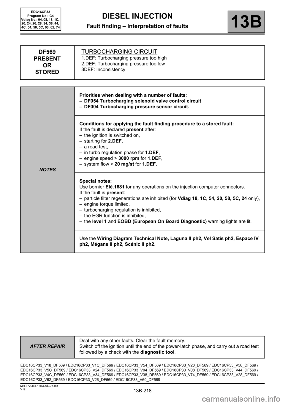
DF569
PRESENT
OR
STOREDTURBOCHARGING CIRCUIT
1.DEF: Turbocharging pressure too high
2.DEF: Turbocharging pressure too low
3DEF: Inconsistency
NOTESPriorities when dealing with a number of faults:
– DF054 Turbocharging solenoid valve control circuit
– DF004 Turbocharging pressure sensor circuit.
Conditions for applying the fault finding procedure to a stored fault:
If the fault is declared present after:
– the ignition is switched on,
– starting for 2.DEF,
– a road test,
– in turbo regulation phase for 1.DEF,
– engine speed > 3000 rpm for 1.DEF,
– system flow > 20 mg/st for 1.DEF.
Special notes:
Use bornier Elé.1681 for any operations on the injection computer connectors.
If the fault is present:
– particle filter regenerations are inhibited (for Vdiag 18, 1C, 54, 20, 58, 5C, 24 only),
– engine torque limited,
– turbocharging regulation is inhibited,
– the EGR function is inhibited,
–the level 1 and EOBD (European On Board Diagnostic) warning lights are lit.
Use the Wiring Diagram Technical Note, Laguna II ph2, Vel Satis ph2, Espace IV
ph2, Mégane II ph2, Scénic II ph2.
EDC16CP33_V18_DF569 / EDC16CP33_V1C_DF569 / EDC16CP33_V54_DF569 / EDC16CP33_V20_DF569 / EDC16CP33_V58_DF569 /
EDC16CP33_V5C_DF569 / EDC16CP33_V24_DF569 / EDC16CP33_V04_DF569 / EDC16CP33_V08_DF569 / EDC16CP33_V44_DF569 /
EDC16CP33_V4C_DF569 / EDC16CP33_V34_DF569 / EDC16CP33_V38_DF569 / EDC16CP33_V74_DF569 / EDC16CP33_V28_DF569 /
EDC16CP33_V62_DF569 / EDC16CP33_V26_DF569 / EDC16CP33_V60_DF569
EDC16CP33
Program No.: C4
Vdiag No.: 04, 08, 18, 1C,
20, 24, 26, 28, 34, 38, 44,
4C, 54, 58, 5C, 60, 62, 74
Page 259 of 510

13B-259
AFTER REPAIRDeal with any other faults. Clear the fault memory.
Switch off the ignition until the end of the power-latch phase, and carry out a road test
followed by a check with the diagnostic tool.
V12 MR-372-J84-13B300$074.mif
DIESEL INJECTION
Fault finding – Interpretation of faults13B
DF1188
PRESENT
OR
STOREDAIR TAKEN INTO THE TURBOCHARGING CIRCUIT
1.DEF: Air leak in the turbocharging circuit
NOTESPriorities when dealing with a number of faults:
– DF004 Turbocharging pressure sensor circuit.
Conditions for applying the fault finding procedure to stored faults:
The fault is declared present with the engine running above 3000 rpm and during the
turbocharger regulation phase (for at least 10 seconds).
Special notes:
If the fault is present:
–the level 1 and OBD warning lights are lit,
– the vehicle performance is reduced,
– engine torque is limited,
– the turbo function is inhibited,
– particle filter regeneration is inhibited,
– the EGR function is inhibited by the engine management computer,
Check the condition of the turbocharging pressure sensor connector (component code 1071).
Check the condition of the turbocharging solenoid valve connector (component code 1475).
Check the condition of the engine management computer connector (component code 120).
If the connectors are faulty and if there is a repair procedure (see Technical Note 6015A, Repairing electrical
wiring, Wiring: Precautions for repair), repair the connector, otherwise replace the wiring.
Check the continuity and insulation of the following connections:
•3LQ between components 120 and 1071,
•3LP between components 120 and 1071,
•3LN between components 120 and 1071,
•3MG between the components 120 and 1475.
If the connection or connections are faulty and there is a repair procedure (see Technical Note 6015A, Electrical
wiring repair, Wiring: Precautions for repair), repair the wiring, otherwise replace it.
EDC16CP33_V20_DF1188 / EDC16CP33_V24_DF1188 / EDC16CP33_V04_DF1188 / EDC16CP33_V08_DF1188 /
EDC16CP33_V44_DF1188 / EDC16CP33_V4C_DF1188 / EDC16CP33_V34_DF1188/ EDC16CP33_V38_DF1188 /
EDC16CP33_V74_DF1188 / EDC16CP33_V60_DF1188 / EDC16CP33_V62_DF1188
EDC16CP33
Program No.: C4
Vdiag No.: 04, 08, 20, 24,
34, 38, 44, 4C, 60, 62, 74
Page 342 of 510

13B-342
AFTER REPAIRCarry out a road test, then check with the diagnostic tool.
V12 MR-372-J84-13B300$121.mif
DIESEL INJECTION
Fault finding – Interpretation of parameters13B
PR035ATMOSPHERIC PRESSURE
PARAMETER
DEFINITIONThis parameter indicates the atmospheric pressure in bar. The sensor is integrated in
the computer.
NOTESSpecial notes:
Only perform these tests if the parameters do not correspond with the system
operation programming.
Conformity check: Engine stopped and ignition on, or engine running, and engine coolant
temperature > 80°C
The atmospheric pressure value must be between:
0.80 bar < PR035 < 1.20 bar.
In the event of a fault, consult the interpretation of fault DF004 Turbocharging pressure sensor circuit and
DF200 Atmospheric pressure sensor.
EDC16CP33_V18_PR035 / EDC16CP33_V1C_PR035 / EDC16CP33_V54_PR035 / EDC16CP33_V20_PR035 / EDC16CP33_V58_PR035 /
EDC16CP33_V5C_PR035 / EDC16CP33_V24_PR035 / EDC16CP33_V04_PR035 / EDC16CP33_V08_PR035 / EDC16CP33_V44_PR035 /
EDC16CP33_V4C_PR035 / EDC16CP33_V34_PR035 / EDC16CP33_V38_PR035 / EDC16CP33_V74_PR035 / EDC16CP33_V28_PR035 /
EDC16CP33_V62_PR035 / EDC16CP33_V26_PR035 / EDC16CP33_V60_PR035
EDC16CP33
Program No.: C4
VDiag No.: 04, 08, 18, 1C,
20, 24, 26, 28, 34, 38, 44,
4C, 54, 58, 5C, 60, 62, 74