2012 RENAULT SCENIC sensor
[x] Cancel search: sensorPage 480 of 510

13B-480
AFTER REPAIRCarry out a road test, then check with the diagnostic tool.
V12 MR-372-J84-13B300$170.mif
DIESEL INJECTION
Fault finding – Fault Finding Chart13B
ALP5 Irregular engine operation
NOTESBefore analysing this customer complaint, check that there are no faults, and the
conformity (or otherwise) of the parameters and statuses, using the diagnostic tool.
If the customer complaint is not eliminated, perform the following checks.
Use the Wiring Diagram Technical Note, Laguna II ph2, Vel Satis ph2, Espace IV
ph2, Mégane II ph2, Scénic II ph2.
If the engine races during gear changes, if there is a floor mat, check that this is not blocking the accelerator pedal,
the brake pedal and the clutch pedal, then check the conformity of the clutch switch and the conformity of the
accelerator pedal sensor when the pedal is released (see PR086 Pedal potentiometer voltage gang 1 and
PR088 Pedal potentiometer voltage gang 2, Sensor supply).
Measure the resistance between connections 3BG and 3BL of component 149.
If the sensor resistance is not between:
741 Ω < X < 905 Ω at +20°C, replace the sensor.
Check the continuity and absence of interference resistance on the following connections:
•3BG between the components 120 and 149,
•3BL between components 120 and 149.
If the connection or connections are faulty and there is a repair procedure (see Technical Note 6015A, Electrical
wiring repair, Wiring: Precautions for repair), repair the wiring, otherwise replace it.
Check the conformity of the engine earths (oxidation, tightness, etc.).
Check the mounting and condition (overheating) of the sensor.
Check the low pressure circuit: run Test 3 Low pressure circuit check.
Apply the air flow checking procedure, (see conformity in the interpretation of statuses and parameters).
Check the turbocharger: apply Test 7 Variable geometry turbocharger control.
If the fault is still present, test the high pressure fuel circuit:
Run scenario SC035 High pressure fuel circuit fault finding.
To interpret the result, apply the interpretation of command SC035 (see Interpretation of commands).
EDC16CP33_V18_ALP05 / EDC16CP33_V1C_ALP05 / EDC16CP33_V54_ALP05 / EDC16CP33_V20_ALP05 / EDC16CP33_V58_ALP05 /
EDC16CP33_V5C_ALP05 / EDC16CP33_V24_ALP05 / EDC16CP33_V04_ALP05 / EDC16CP33_V08_ALP05 / EDC16CP33_V44_ALP05 /
EDC16CP33_V4C_ALP05 / EDC16CP33_V34_ALP05 / EDC16CP33_V38_ALP05 / EDC16CP33_V74_ALP05 / EDC16CP33_V28_ALP05 /
EDC16CP33_V62_ALP05 / EDC16CP33_V26_ALP05 / EDC16CP33_V60_ALP05
EDC16CP33
Program No.: C4
Vdiag No.: 04, 08, 18, 1C,
20, 24, 26, 28, 34, 38, 44,
4C, 54, 58, 5C, 60, 62, 74
Page 484 of 510

13B-484
AFTER REPAIRCarry out a road test, then check with the diagnostic tool.
V12 MR-372-J84-13B300$170.mif
DIESEL INJECTION
Fault finding – Fault Finding Chart13B
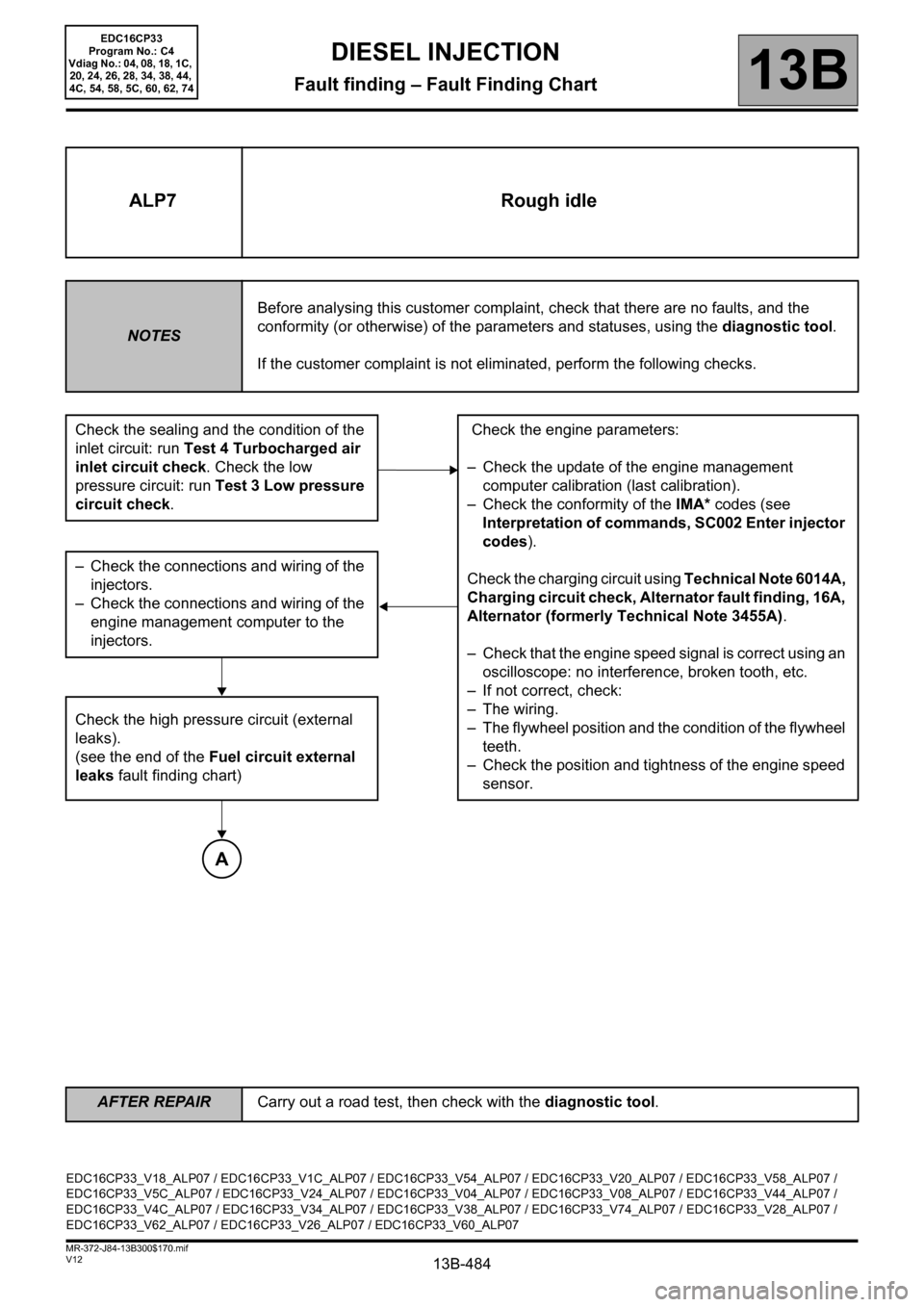
ALP7 Rough idle
NOTESBefore analysing this customer complaint, check that there are no faults, and the
conformity (or otherwise) of the parameters and statuses, using the diagnostic tool.
If the customer complaint is not eliminated, perform the following checks.
Check the sealing and the condition of the
inlet circuit: run Test 4 Turbocharged air
inlet circuit check. Check the low
pressure circuit: run Test 3 Low pressure
circuit check. Check the engine parameters:
– Check the update of the engine management
computer calibration (last calibration).
– Check the conformity of the IMA* codes (see
Interpretation of commands, SC002 Enter injector
codes).
Check the charging circuit using Technical Note 6014A,
Charging circuit check, Alternator fault finding, 16A,
Alternator (formerly Technical Note 3455A).
– Check that the engine speed signal is correct using an
oscilloscope: no interference, broken tooth, etc.
– If not correct, check:
– The wiring.
– The flywheel position and the condition of the flywheel
teeth.
– Check the position and tightness of the engine speed
sensor. – Check the connections and wiring of the
injectors.
– Check the connections and wiring of the
engine management computer to the
injectors.
Check the high pressure circuit (external
leaks).
(see the end of the Fuel circuit external
leaks fault finding chart)
A
EDC16CP33_V18_ALP07 / EDC16CP33_V1C_ALP07 / EDC16CP33_V54_ALP07 / EDC16CP33_V20_ALP07 / EDC16CP33_V58_ALP07 /
EDC16CP33_V5C_ALP07 / EDC16CP33_V24_ALP07 / EDC16CP33_V04_ALP07 / EDC16CP33_V08_ALP07 / EDC16CP33_V44_ALP07 /
EDC16CP33_V4C_ALP07 / EDC16CP33_V34_ALP07 / EDC16CP33_V38_ALP07 / EDC16CP33_V74_ALP07 / EDC16CP33_V28_ALP07 /
EDC16CP33_V62_ALP07 / EDC16CP33_V26_ALP07 / EDC16CP33_V60_ALP07
EDC16CP33
Program No.: C4
Vdiag No.: 04, 08, 18, 1C,
20, 24, 26, 28, 34, 38, 44,
4C, 54, 58, 5C, 60, 62, 74
Page 490 of 510

13B-490
AFTER REPAIRCarry out a road test, then check with the diagnostic tool.
V12 MR-372-J84-13B300$170.mif
DIESEL INJECTION
Fault finding – Fault Finding Chart13B
IMA*: Individual injector correction
ALP9
CONTINUED 3
– Check the consistency between the IMA* codes entered and the codes engraved on the injector bodies.
– Check that the particle filter differential pressure sensor is correctly positioned and connected (see MR 395, 402,
405, 364 or 370 Mechanical, 19B Exhaust, Particle filter pressure sensor: Removal - Refitting),
– Check the exhaust pipe (see TEST1 Exhaust pipe check),
– Check the air inlet circuit (see TEST4 Turbocharged air inlet circuit check),
– Check the air flowmeter (see TEST5 Air flowmeter),
– Check the turbocharger (see TEST7 Variable geometry turbocharger check),
– Check the injectors (see TEST10 Poor injector operation),
– Check the cylinder compressions.
If the fault has not been located and the customer complaint is still present, contact the Techline.
YES
E
EDC16CP33
Program No.: C4
Vdiag No.: 18, 1C, 20, 24,
26, 28, 54, 58, 5C, 60, 62
Page 492 of 510

13B-492V12 MR-372-J84-13B300$180.mif
13B
*Technical Note 3419: Fault finding on the turbocharger for petrol and diesel engines. EXHAUST SYSTEM CHECK TEST1
RESOLVING MISFIRESTEST2
LOW PRESSURE CIRCUIT CHECK TEST3
TURBOCHARGED AIR INLET CIRCUIT CHECK TEST4
AIR FLOW SENSORTEST5
FUEL RETURN RAIL VALVE CHECK TEST6
VARIABLE GEOMETRY TURBOCHARGER CONTROLTEST 7: Apply
TEST 4 of
Technical Note
3419*
ROTATING PART OF TURBOCHARGERTEST 8: Apply
TEST 7 of
Technical Note
3419*
POOR INJECTOR OPERATION TEST10
TEMPERATURE UPSTREAM OF TURBINE TOO LOW TEST11
DIESEL FUEL CONFORMITY CHECK TEST12
DIESEL INJECTION
Fault finding – Test
EDC16CP33
Program No.: C4
Vdiag No.: 04, 08, 18, 1C,
20, 24, 26, 28, 34, 38, 44,
4C, 54, 58, 5C, 60, 62, 74
Page 497 of 510

13B-497V12 MR-372-J84-13B300$180.mif
DIESEL INJECTION
Fault finding – Test13B
TEST3 Low pressure circuit check
Check the fuel filter:
– Conformity of the fuel filter (correct part number and RENAULT filter).
– Positioning and degree of clogging of the filter cartridge.
– Positioning and condition of the seals.
– If there is metal swarf in the filter:
Replace the fuel filter, bleed the circuit and continue the fault finding procedure.
Supplying the injection system with fuel from an additional tank.
This operation aims to detect possible faults in the low pressure supply system of a vehicle by replacing it entirely
with an additional tank.
Mode:
– Disconnect the diesel fuel supply pipe at the fuel filter inlet and block it with a plug.
– Connect a pipe to the fuel filter inlet and insert the other end in a clean container with a capacity of approximately
5 litres.
– Disconnect the diesel fuel return pipe at the diesel temperature sensor (pump return and injector return join), and
block it using a plug.
– Connect a transparent pipe to the union of the diesel fuel temperature sensor, and insert the other end in the
container.
– Fill the container with clean diesel fuel.
– Start the engine and let the system drain itself of its air (there must not be any air bubbles in the return pipe).
Is the customer complaint still present?If the low pressure circuit is in order, reconnect the
various low pressure circuit pipes, and repeat the
fault finding chart procedure or the procedure for
the fault that referred you to this test.
Are the low pressure circuit connections in order
and in good condition?Carry out the necessary repairs.
YES
NO
NO
A
YES
EDC16CP33_V18_TEST3 / EDC16CP33_V1C_TEST3 / EDC16CP33_V54_TEST3 / EDC16CP33_V20_TEST3 / EDC16CP33_V58_TEST3 /
EDC16CP33_V5C_TEST3 / EDC16CP33_V24_TEST3 / EDC16CP33_V04_TEST3 / EDC16CP33_V08_TEST3 / EDC16CP33_V44_TEST3 /
EDC16CP33_V4C_TEST3 / EDC16CP33_V34_TEST3 / EDC16CP33_V38_TEST3 / EDC16CP33_V74_TEST3 / EDC16CP33_V28_TEST3 /
EDC16CP33_V62_TEST3 / EDC16CP33_V26_TEST3 / EDC16CP33_V60_TEST3
EDC16CP33
Program No.: C4
Vdiag No.: 04, 08, 18, 1C,
20, 24, 26, 28, 34, 38, 44,
4C, 54, 58, 5C, 60, 62, 74
Page 499 of 510

13B-499V12 MR-372-J84-13B300$180.mif
DIESEL INJECTION
Fault finding – Test13B
TEST4 Turbocharged air inlet circuit check
Engine stopped: Check the sealing (leak or air intake) of the low and high pressure air circuit (before/after
turbocharger).
Check the parts that are abnormally greasy of the circuit and reveal a lack of tightness.
Check:
– the condition and fitting of the ducts (foreign, clogged, not joined, kinked, broken, pierced, cut bodies, tightness
of the mounting bolts, etc.).
– the presence, condition and fitting of the seals.
– the present and tightening of the clamps.
– The fitting of the turbocharging pressure sensor.
– The pipes and the take-off point between the air duct and the turbocharging sensor.
Carry out the necessary repairs.
Check the air filter.
Check:
– That the inlet and outlet of the air filter unit is not blocked.
– the condition and the assembly of the air filter unit (disconnected, broken, pierced …).
– The cleanliness, the conformity and the non-distortion of the filter element.
– The air flowmeter: run Test 5 Air flowmeter.
Carry out the necessary repairs
Check:
– the condition of the damper valve,
– the tightening of the mounting bolts,
– cracks in the damper valve.
Carry out the necessary repairs.
A
EDC16CP33_V18_TEST4 / EDC16CP33_V1C_TEST4 / EDC16CP33_V54_TEST4 / EDC16CP33_V20_TEST4 / EDC16CP33_V58_TEST4 /
EDC16CP33_V5C_TEST4 / EDC16CP33_V24_TEST4 / EDC16CP33_V04_TEST4 / EDC16CP33_V08_TEST4 / EDC16CP33_V44_TEST4 /
EDC16CP33_V4C_TEST4 / EDC16CP33_V34_TEST4 / EDC16CP33_V38_TEST4 / EDC16CP33_V74_TEST4 / EDC16CP33_V28_TEST4 /
EDC16CP33_V62_TEST4 / EDC16CP33_V26_TEST4 / EDC16CP33_V60_TEST4
EDC16CP33
Program No.: C4
Vdiag No.: 04, 08, 18, 1C,
20, 24, 26, 28, 34, 38, 44,
4C, 54, 58, 5C, 60, 62, 74
Page 500 of 510

13B-500V12 MR-372-J84-13B300$180.mif
DIESEL INJECTION
Fault finding – Test13B
TEST4
CONTINUEDTurbocharged air inlet circuit check
Check that there is no leak at the exhaust manifold, in particular at the exhaust manifold/turbocharger connection.
Check the exhaust, run Test 1 Exhaust pipe check.
Carry out the necessary repairs.
Visually check the EGR circuit sealing.
Note:
The operational clearance of the EGR exchanger flap shaft leaves slight traces of a black substance due to
inconsequential leakage. Do not replace this part.
– Check the condition of the intercooler:
– clogging,
– leaks (vehicle stationary, stabilise the engine speed between 3500 rpm and 4000 rpm and check that there are
no leaks).
Replace if necessary.
Check that the turbocharging pressure sensor take-off point is not blocked.
Carry out the necessary repairs
END OF TEST.
A
EDC16CP33
Program No.: C4
Vdiag No.: 04, 08, 18, 1C,
20, 24, 26, 28, 34, 38, 44,
4C, 54, 58, 5C, 60, 62, 74
Page 501 of 510

13B-501V12 MR-372-J84-13B300$180.mif
DIESEL INJECTION
Fault finding – Test13B
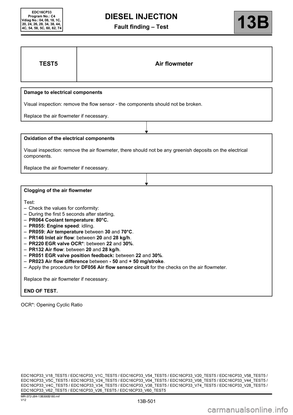
OCR*: Opening Cyclic Ratio
TEST5 Air flowmeter
Damage to electrical components
Visual inspection: remove the flow sensor - the components should not be broken.
Replace the air flowmeter if necessary.
Oxidation of the electrical components
Visual inspection: remove the air flowmeter, there should not be any greenish deposits on the electrical
components.
Replace the air flowmeter if necessary.
Clogging of the air flowmeter
Test:
– Check the values for conformity:
– During the first 5 seconds after starting,
–PR064 Coolant temperature: 80°C.
–PR055: Engine speed: idling.
–PR059: Air temperature between 30 and 70°C.
–PR146 Inlet air flow: between 20 and 28 kg/h.
–PR220 EGR valve OCR*: between 22 and 30%.
–PR132 Air flow: between 20 and 28 kg/h.
–PR051 EGR valve position feedback: between 22 and 30%.
–PR023 Air flow difference between - 50 and + 50 mg/stroke.
– Apply the procedure for DF056 Air flow sensor circuit for the checks on the air flowmeter.
Replace the air flowmeter if necessary.
END OF TEST.
EDC16CP33_V18_TEST5 / EDC16CP33_V1C_TEST5 / EDC16CP33_V54_TEST5 / EDC16CP33_V20_TEST5 / EDC16CP33_V58_TEST5 /
EDC16CP33_V5C_TEST5 / EDC16CP33_V24_TEST5 / EDC16CP33_V04_TEST5 / EDC16CP33_V08_TEST5 / EDC16CP33_V44_TEST5 /
EDC16CP33_V4C_TEST5 / EDC16CP33_V34_TEST5 / EDC16CP33_V38_TEST5 / EDC16CP33_V74_TEST5 / EDC16CP33_V28_TEST5 /
EDC16CP33_V62_TEST5 / EDC16CP33_V26_TEST5 / EDC16CP33_V60_TEST5
EDC16CP33
Program No.: C4
Vdiag No.: 04, 08, 18, 1C,
20, 24, 26, 28, 34, 38, 44,
4C, 54, 58, 5C, 60, 62, 74