2012 Peugeot 207 CC fuse
[x] Cancel search: fusePage 5 of 224

3
CONTENTS
Direction indicators 93
Emergency or assistance
call 93
Hazard warning lamps 94
Horn 94
Tyre under-infl ation detection 95
Braking assistance
systems 96
Trajectory control
systems 97
Seat belts 98
Airbags 101■
■
■
■
■
■
■
■
■
SAFETY 93 �Π104
Parking brake 105
Manual gearbox 105
Gear shift indicator 106
Automatic gearbox 107
Speed limiter 110
Cruise control 112
Parking sensors 114■
■
■
■
■
■
■
DRIVING 105 �Π11 5
Bonnet 117
Running out of fuel (Diesel) 117
Petrol engines 118
Diesel engine 119
Checking levels 120
Checks 121■
■
■
■
■
■
CHECKS
116 �Π122
Temporary puncture
repair kit 123
Changing a wheel 128
Changing a bulb 132
Changing a fuse 136
Battery 141
Energy economy mode 143
Changing a wiper blade 143
Towing the vehicle 144
Towing a trailer 145
Accessories 147■
■
■
■
■
■
■
■
■
■
PRACTICAL
INFORMATION 123 �Π147
Petrol engines 148
Weights (petrol) 149
Diesel engine 150
Weights (Diesel) 151
Dimensions 152
Identifi cation markings 153■
■
■
■
■
■
TECHNICAL
D ATA 148 �Π154
AUDIO EQUIPMENT
and TELEMATICS 155 �Π210
Emergency or assistance 155Peugeot Connect Navigation (RNEG) 157
Peugeot Connect Sound (RD5) 189■
■
■
ALPHABETICAL
INDEX 215 �Π218
7
86
9
10
VISUAL
SEARCH 211 �Π214
Page 8 of 224

! !
i
6
FAMILIARISATION
OPENING
Retractable roof
When washing your vehicle:
- lock the vehicle,
- avoid spraying the upper part
of the windows,
- keep the end of the high-pres-
sure nozzle at least 1 metre
from the windows and door
seals.
After washing the vehicle or fol-
lowing rain, wait until the roof has
dried before opening it. The roof is operated under the
sole responsibility of the driver.
During operation of the roof, to
avoid the risk of injury, ensure
that no one is in the vicinity of the
moving parts.
You are strongly advised not to
operate the roof in strong winds. It is preferable to operate the roof
with the engine running.
The roof can be operated at
speeds below 6 mph (10 km/h).
It is only possible to carry out the
operation twice with the engine off,
to prevent discharging of the bat-
tery.
Preliminary conditions
�)
Switch on the ignition.
�)
Ensure that:
- the vehicle is not in energy econo-
my mode (refer to the correspond-
ing section),
- the battery voltage is suffi cient
(switching on of the indicator lamp
on the roof control),
- the roof fuse is in good condition (re-
fer to the corresponding section),
- the electric windows are initialised
(refer to the corresponding section),
- the ambient temperature is above
-15 °C.
Precautions to be taken before
operating the roof
�)
Park the vehicle on level ground.
�)
Check that no object could hinder
the operation of the roof:
- nothing should be placed on the
moving rear shelf 1
or on the net 2
,
- if luggage is being carried in the
boot, it must not raise the net,
�)
Ensure that the net 2
is secure.
�)
Close the boot correctly.
Maintenance
Carry out a complete roof opera-
tion at least once a month to keep
it in good working order.
Page 12 of 224

10
FAMILIARISATION
INSTRUMENTS AND CONTROLS
1.
Steering wheel adjustments control.
2.
Cruise control/speed limiter
switches.
3.
Lighting and direction indicators
control stalk.
4.
Hazard warning lamps switch.
5.
Multifunction screen.
Seat belt fastening status warning
lamps.
6.
Sunshine sensor.
7.
Passenger’s airbag.
8.
Speaker (medium tweeter).
9.
Glove box/Passenger’s airbag
deactivation/Audio/video sockets/
Fusebox.
10.
Bonnet release lever.
11 .
12 V accessory socket.
12.
USB port.
13.
Heating/air conditioning controls.
14.
Storage compartment.
15.
Audio and telematics system.
16.
Central adjustable air vents.
Page 47 of 224

2COMFORT
45
VENTILATION
Air treatment
The incoming air follows various routes
depending on the controls selected by
the driver:
- direct arrival in the passenger com-
partment (air intake),
- passage through a heating circuit
(heating),
- passage through a cooling circuit
(air conditioning). The temperature control enables you to
obtain the level of comfort required by
mixing the air of the various circuits.
The air distribution control enables you
to diffuse the air in the passenger com-
partment combining several air vents.
The air fl ow control enables you to in-
crease or reduce the speed of the ven-
tilation blower.
Air intake
The air circulating in the passenger com-
partment is fi ltered and originates either
from the outside via the grille located at
the base of the windscreen or from the
inside in air recirculation mode.
Control panel
The controls of this system are grouped
together on control panel A
on the cen-
tre console. Depending on the model,
the functions offered are:
- the level of comfort required,
- air fl ow,
- air distribution,
- demisting-defrosting,
- manual or digital air conditioning
controls.
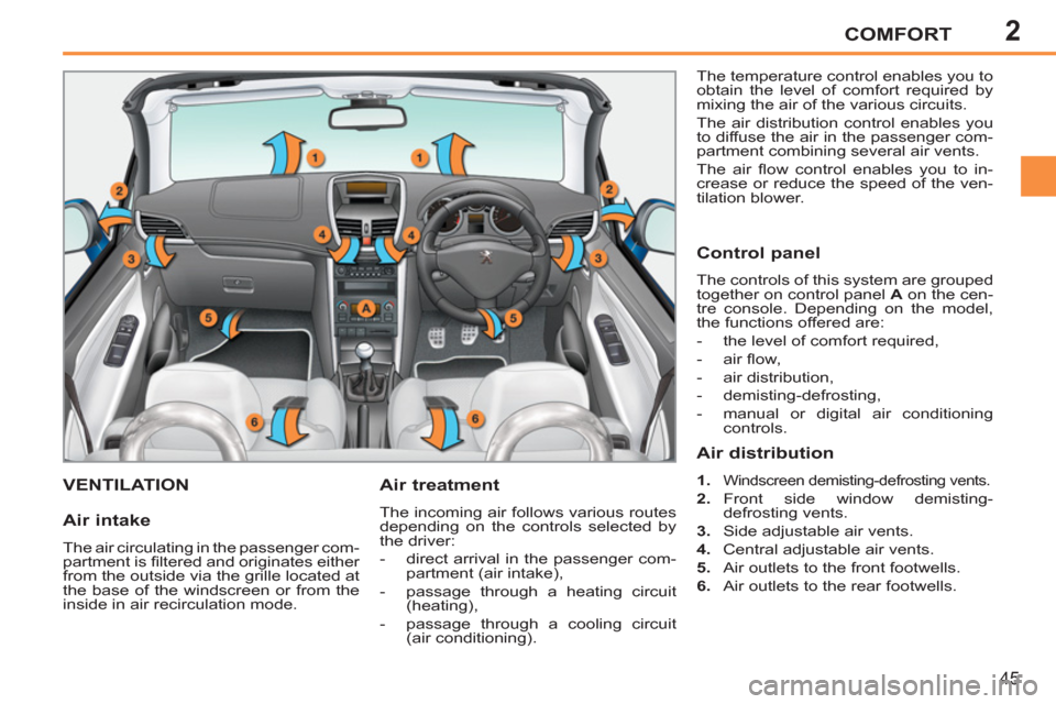
Air distribution
1.
Windscreen demisting-defrosting vents.
2.
Front side window demisting-
defrosting vents.
3.
Side adjustable air vents.
4.
Central adjustable air vents.
5.
Air outlets to the front footwells.
6.
Air outlets to the rear footwells.
Page 61 of 224

2COMFORT
59
Illuminated glove box
This has an upper open storage com-
partment and locations for storing a
small bottle of water, the vehicle’s hand-
book, ...
Its lid has locations for a pen, tokens,
cards, cans, ...
12 V accessory socket
�)
To connect a 12 V accessory (max
power: 120 Watts), lift the cover and
connect a suitable adaptor.
The "AUX"
connection box, located in
the centre console, comprises an auxil-
iary JACK socket and/or a USB port.
It permits the connection of a portable
device, such as a digital audio player of
the iPod
® or USB memory stick type.
It reads certain audio fi le formats allow-
ing them to be heard via the vehicle's
speakers.
You can manage these fi les using the
steering mounted controls or the audio
system control panel and display them
in the multifunction screen.
Connected to the USB port, the port-
able device charges automatically while
in use.
For more information on the use of
this equipment, refer to the "Audio and
Telematics" section. It is fi tted with a lock.
�)
To open the glove box, raise the
handle.
It is illuminated when the lid is opened.
It houses the front passenger airbag de-
activation switch A
.
If the vehicle is fi tted with air condi-
tioning, it provides access to the ven-
tilation nozzle B
, which can be opened
or closed, distributing the same condi-
tioned air as the vents in the passenger
compartment.
It also provides access to the dashboard
fusebox (refer to "Changing a fuse").
Page 120 of 224

8CHECKS
118
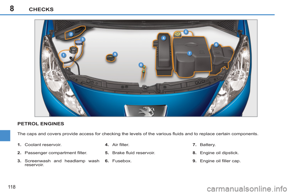
PETROL ENGINES
The caps and covers provide access for checking the levels of the various fl uids and to replace certain components.
1.
Coolant reservoir.
2.
Passenger compartment fi lter.
3.
Screenwash and headlamp wash
reservoir.
4.
Air fi lter.
5.
Brake fl uid reservoir.
6.
Fusebox.
7.
Battery.
8.
Engine oil dipstick.
9.
Engine oil fi ller cap.
Page 121 of 224

8CHECKS
119
DIESEL ENGINE
The caps and covers provide access for checking the levels of the various fl uids, to replace certain components and to prime
the fuel system.
1.
Coolant reservoir.
2.
Passenger compartment fi lter.
3.
Screenwash and headlamp wash
reservoir.
4.
Priming pump.
5.
Brake fl uid reservoir.
6.
Fusebox.
7.
Battery.
8.
Engine oil dipstick.
9.
Engine oil fi ller cap.
10.
Air fi lter.
Page 138 of 224

9
!
i
i
PRACTICAL INFORMATION
136
PEUGEOT does not accept any
responsibility for the costs incurred
in repairing your vehicle or for the
malfunctions resulting from the in-
stallation of additional accessories
which are not supplied or recom-
mended by PEUGEOT and which
are not installed in accordance with
its instructions, particularly when
the combined consumption of all of
the additional equipment connect-
ed exceeds 10 milliamperes.
Installation of electrical acces-
sories
Your vehicle’s electrical circuit is
designed to operate with the stand-
ard or optional equipment.
Before installing other electrical
equipment or accessories in your
vehicle, contact a PEUGEOT deal-
er or a qualifi ed workshop.
CHANGING A FUSE
Procedure for the replacement of a
faulty fuse with a new fuse in order to
rectify a failure of the corresponding
function.
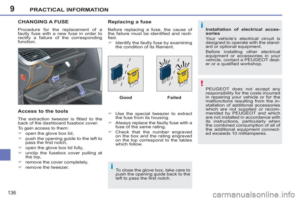
Access to the tools
The extraction tweezer is fi tted to the
back of the dashboard fusebox cover.
To gain access to them:
�)
open the glove box lid,
�)
push the opening guide to the left to
pass the fi rst notch,
�)
open the glove box lid fully,
�)
unclip the fusebox cover pulling at
the top,
�)
remove the cover completely,
�)
remove the tweezer.
Replacing a fuse
Before replacing a fuse, the cause of
the failure must be identifi ed and recti-
fi ed.
�)
Identify the faulty fuse by examining
the condition of its fi lament.
�)
Use the special tweezer to extract
the fuse from its housing.
�)
Always replace the faulty fuse with a
fuse of the same rating.
�)
Check that the number engraved
on the box and the rating engraved
on the top correspond to the tables
which follow.
Good
Failed
To close the glove box, take care to
push the opening guide back to the
left to pass the fi rst notch.