2012 NISSAN QASHQAI Reverse
[x] Cancel search: ReversePage 203 of 297

Downloaded from www.Manualslib.com manuals search engine and varies the brake fluid pressure to prevent each
wheel from locking and sliding. By preventing each
wheel from locking, the system helps the driver to
maintain steering control and helps to minimise
swerving and spinning on slippery surfaces.
Using the system
Depress the brake pedal and hold it down. Depress
the brake pedal with firm steady pressure, but do
not pump the brakes. The ABS will operate to pre-
vent the wheels from locking up. Steer the vehicle to
avoid obstacles.
WARNING
Do not pump the brake pedal. Doing so may in-
crease the stopping distance.
Self-test feature
The ABS includes electronic sensors, electric
pumps, hydraulic solenoids and a computer. The
computer has a built-in diagnostic feature that tests
the system each time you start the engine and move
thevehicleatalowspeedinforwardorreverse.
When the self-test occurs, you may hear a “clunk”
noise and/or feel a pulsation in the brake pedal. This
is normal and does not indicate a malfunction. If the
computer senses a malfunction, it switches the ABS
off and illuminates the ABS warning light on the
instrument panel. The brake system then operates
normally, but without anti-lock assistance.
If the ABS warning light illuminates during the self-
test or while driving, have the vehicle checked by a
NISSAN dealer or qualified workshop.
Normal operation
The ABS will not initiate at speeds below 5 to 10
km/h (3 to 6 MPH). The speeds will vary according
to road conditions.
When the ABS senses that one or more wheels are
close to locking up, the actuator rapidly applies and
releases hydraulic pressure. This action is similar to
pumping the brakes very quickly. You may feel a
pulsation in the brake pedal and hear a noise from
the actuator under the bonnet when it is operating.
This is normal and indicates that the ABS is working
properly. However, the pulsation may indicate that
road conditions are hazardous and extra care is re-
quired while driving. When accelerating, driving on slippery surfaces or
suddenly avoiding obstacles on roads, the vehicle
might swerve or slip. The Electronic Stability Pro-
gramme (ESP) system continuously monitors and
compares the driver’s intended speed and the travel
direction. The system adjusts wheel brake pressure
and engine torque to assist in improving vehicle sta-
bility.
When the ESP system is operating, the “SLIP”
indicator light () in the combination meter
blinks.
When only the traction control (TCS) system in
the ESP system is operating, the “SLIP” indica-
tor light (
) in the combination meter will also
blink.
If the “SLIP” indicator light () blinks, the
road conditions are slippery. Be sure to drive
carefully. See “Warning/indicator lights and au-
dible reminders” in the “2. Instruments and
controls” section.
Indicator light
If a malfunction occurs in the system, the “SLIP”
indicator light (
) and the ESP indicator light
() come on in the combination meter.
As long as these indicator lights are on, the trac-
tion control function is cancelled.
The ESP system uses Active Brake Limited Slip
(ABLS) system to improve vehicle traction. The Ac-
tive Brake Limited Slip (ABLS) system works when
one of the driving wheels is spinning on a slippery
ELECTRONIC STABILITY
PROGRAMME (ESP) SYSTEM
(where fitted)
5-40Starting and driving
Page 204 of 297
Downloaded from www.Manualslib.com manuals search engine surface. The Active Brake Limited Slip (ABLS) sys-
tem, brakes the spinning wheel to distribute the driv-
ing power to the other driving wheel.
If the vehicle is operated with the ESP system turned
off, all ESP and TCS functions will be turned off.
The Active Brake Limited Slip (ABLS) system and
ABS will still operate with the ESP system off. If the
Active Brake Limited Slip (ABLS) system or the ABS
is activated, the “SLIP” indicator light (
) will
blink and you may hear a clunk noise and/or feel a
pulsation in the brake pedal. This is normal and does
not indicate a malfunction.
While the ESP system is operating, you may feel a
pulsation in the brake pedal and hear a noise or
vibration from under the bonnet. This is normal and
indicates that the ESP system is working properly.
The ESP computer has a built in diagnostic feature
that tests the system each time the engine is started
and the vehicle moves forwards or reverses at a
slow speed. When the self-test occurs, you may
hear a clunk noise and/or feel a pulsation in the
brake pedal. This is normal and is not an indication
of a malfunction.
WARNING
The ESP system is designed to help improve
driving stability but does not prevent accidents
caused by abrupt steering operation at high
speeds, or careless or dangerous driving
techniques. Reduce vehicle speed and be es-
pecially careful when driving and cornering on
slippery surfaces. Always drive carefully.
If engine related parts, such as a muffler, are
not standard equipment or are extremely de-
teriorated, the ESP OFF indicator light (
)
and/or the “SLIP” indicator light () may
illuminate.
If brake related parts, such as brake pads,
rotors and callipers, are not standard equip-
ment or are extremely deteriorated, the ESP
system may not operate properly and the ESP
OFF indicator light (
) and/or the “SLIP”
indicator light () may illuminate.
Do not modify the vehicle’s suspension. If
suspension parts, such as shock absorbers,
struts, springs, stabiliser bars and bushings,
are not NISSAN-approved or are extremely
deteriorated, the ESP system may not oper-
ate properly. This could adversely affect ve-
hicle handling performance and the ESP OFF
indicator light (
) and/or the “SLIP” indi-
cator light () may illuminate.
When driving on extremely inclined surfaces,
such as higher banked corners, the ESP sys-
tem may not operate properly and the ESP
OFF indicator light (
) and/or the “SLIP”
indicator light () may illuminate. Do not
drive on these types of roads. If ESP OFF indi-
cator light
does illuminate after driving
on extreme surfaces, restart the engine to re-
set the ESP system.
If wheels or tyres other than the
recommended ones are used, the ESP sys-
tem may not operate properly and the ESP OFF indicator light (
) and/or the “SLIP”
indicator light () may illuminate.
The ESP system is not a substitute for winter
tyres or snow chains on a snow covered road.
NOTE
The ESP system should be switched on under
normal circumstances although it may be ad-
vantageous to switch off the ESP system to
allow wheelspin under the following condi-
tions:
– When driving in deep snow or mud.
– When trying to rock a vehicle free that is stuck in snow.
– When driving with snow chains.
If the ESP system has been switched off, drive
carefully with reduced speed. When road con-
ditions allow, ESP should be switched back
on.
Starting and driving5-41
Page 209 of 297
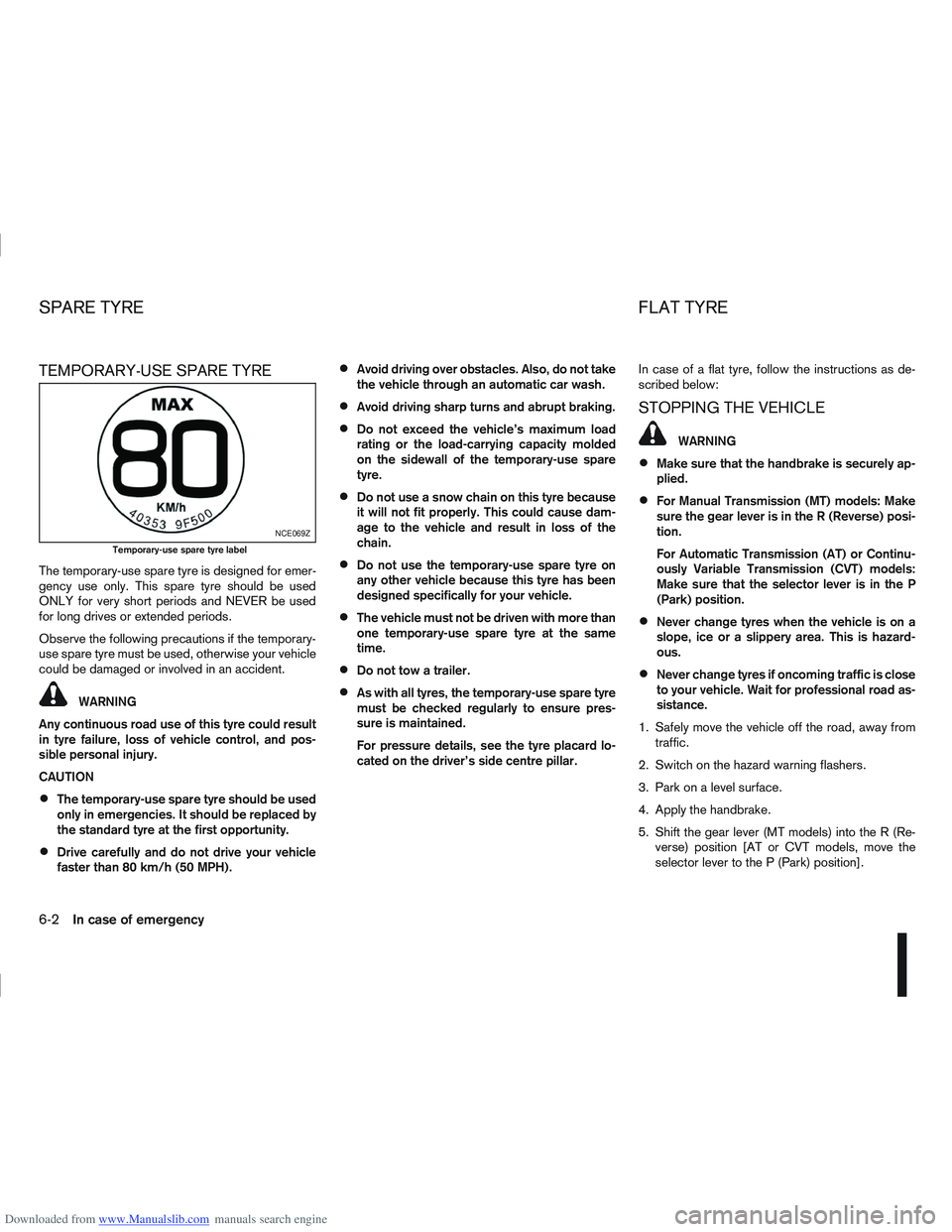
Downloaded from www.Manualslib.com manuals search engine TEMPORARY-USE SPARE TYRE
The temporary-use spare tyre is designed for emer-
gency use only. This spare tyre should be used
ONLY for very short periods and NEVER be used
for long drives or extended periods.
Observe the following precautions if the temporary-
use spare tyre must be used, otherwise your vehicle
could be damaged or involved in an accident.
WARNING
Any continuous road use of this tyre could result
in tyre failure, loss of vehicle control, and pos-
sible personal injury.
CAUTION
The temporary-use spare tyre should be used
only in emergencies. It should be replaced by
the standard tyre at the first opportunity.
Drive carefully and do not drive your vehicle
faster than 80 km/h (50 MPH).
Avoid driving over obstacles. Also, do not take
the vehicle through an automatic car wash.
Avoid driving sharp turns and abrupt braking.
Do not exceed the vehicle’s maximum load
rating or the load-carrying capacity molded
on the sidewall of the temporary-use spare
tyre.
Do not use a snow chain on this tyre because
it will not fit properly. This could cause dam-
age to the vehicle and result in loss of the
chain.
Do not use the temporary-use spare tyre on
any other vehicle because this tyre has been
designed specifically for your vehicle.
The vehicle must not be driven with more than
one temporary-use spare tyre at the same
time.
Do not tow a trailer.
As with all tyres, the temporary-use spare tyre
must be checked regularly to ensure pres-
sure is maintained.
For pressure details, see the tyre placard lo-
cated on the driver’s side centre pillar. In case of a flat tyre, follow the instructions as de-
scribed below:
STOPPING THE VEHICLE
WARNING
Make sure that the handbrake is securely ap-
plied.
For Manual Transmission (MT) models: Make
sure the gear lever is in the R (Reverse) posi-
tion.
For Automatic Transmission (AT) or Continu-
ously Variable Transmission (CVT) models:
Make sure that the selector lever is in the P
(Park) position.
Never change tyres when the vehicle is on a
slope, ice or a slippery area. This is hazard-
ous.
Never change tyres if oncoming traffic is close
to your vehicle. Wait for professional road as-
sistance.
1. Safely move the vehicle off the road, away from traffic.
2. Switch on the hazard warning flashers.
3. Park on a level surface.
4. Apply the handbrake.
5. Shift the gear lever (MT models) into the R (Re- verse) position [AT or CVT models, move the
selector lever to the P (Park) position].
NCE069Z
Temporary-use spare tyre label
SPARE TYRE FLAT TYRE
6-2In case of emergency
Page 251 of 297
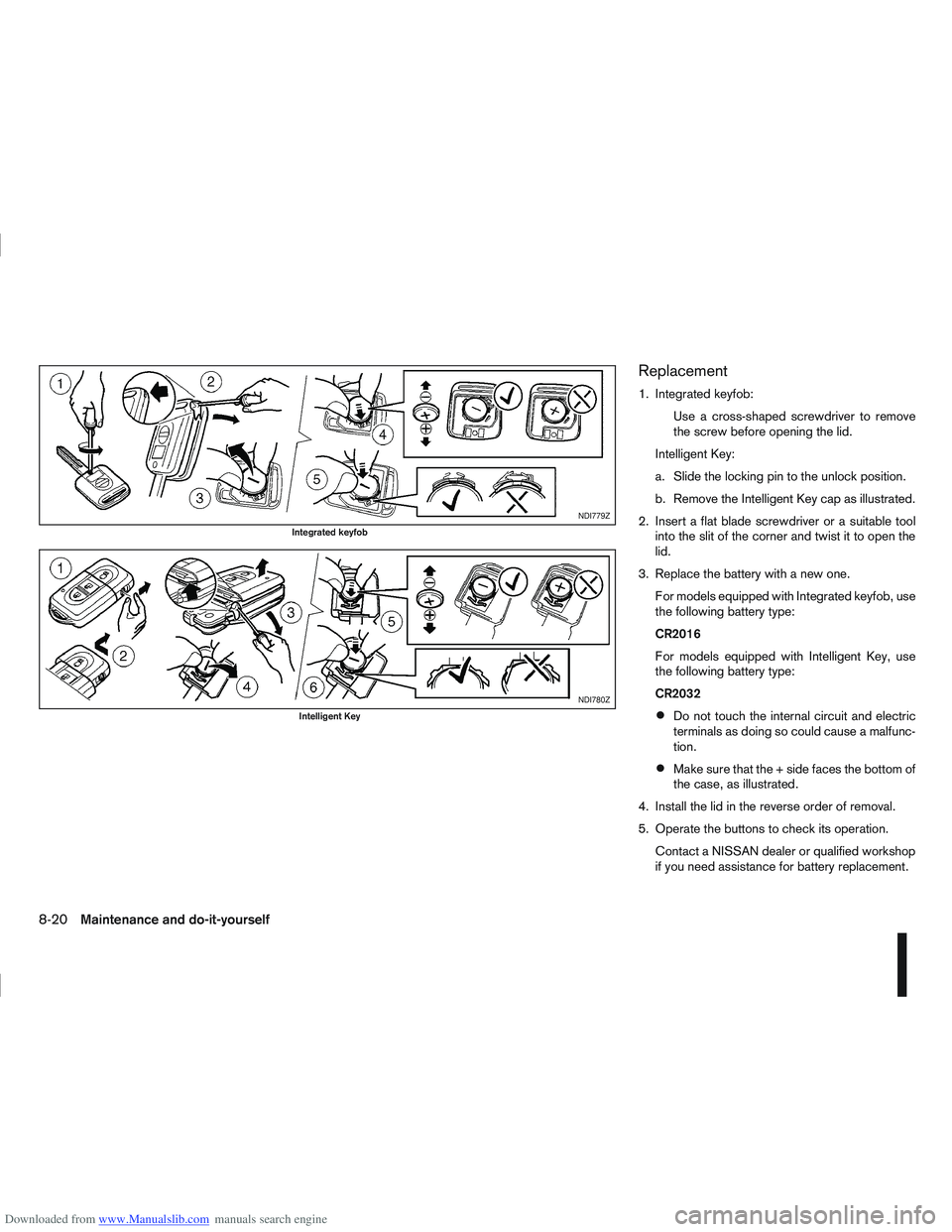
Downloaded from www.Manualslib.com manuals search engine Replacement
1. Integrated keyfob:Use a cross-shaped screwdriver to remove
the screw before opening the lid.
Intelligent Key:
a. Slide the locking pin to the unlock position.
b. Remove the Intelligent Key cap as illustrated.
2. Insert a flat blade screwdriver or a suitable tool into the slit of the corner and twist it to open the
lid.
3. Replace the battery with a new one. For models equipped with Integrated keyfob, use
the following battery type:
CR2016
For models equipped with Intelligent Key, use
the following battery type:
CR2032
Do not touch the internal circuit and electric
terminals as doing so could cause a malfunc-
tion.
Make sure that the + side faces the bottom of
the case, as illustrated.
4. Install the lid in the reverse order of removal.
5. Operate the buttons to check its operation. Contact a NISSAN dealer or qualified workshop
if you need assistance for battery replacement.
NDI779Z
Integrated keyfob
NDI780Z
Intelligent Key
8-20Maintenance and do-it-yourself
Page 253 of 297

Downloaded from www.Manualslib.com manuals search engine Be careful when working on the engine with-
out the air cleaner filter.
VISCOUS PAPER TYPE
The filter elementjA should not be cleaned and
reused.
Replace it according to the maintenance schedule
shown in the separately provided Warranty Informa-
tion & Maintenance Booklet. When replacing the fil-
ter, wipe the inside of the air cleaner housing and
the cover with a damp cloth.
DRY PAPER TYPE (where fitted)
Check the filter elementjA to see if it is dirty. If it is
dirty, shake the element to remove dust.
Clean or replace it according to the maintenance
schedule shown in the separately provided War-
ranty Information & Maintenance Booklet. When
cleaning or replacing the filter, wipe the inside of the
air cleaner housing and the cover with a damp cloth.
CLEANING
If the windscreen or back door window is not clear
after using the window washer or if a wiper blade
chatters when running, wax or other material may be
on the blade or windscreen.
Clean the outside of the windscreen or back door
window with a washer solution or a mild detergent.
The windscreen or back door window is clean if
beads do not form when rinsing with clear water.
Clean the blade by wiping it with a cloth soaked in a
washer solution or a mild detergent. Then rinse the
blade with clear water. If the windscreen or back
door window is still not clear after cleaning the
blades and using the wiper, replace the blades.
CAUTION
After wiper blade replacement, return the
wiper arm to its original position. Otherwise it
may be damaged when the bonnet is opened.
Make sure the wiper blade contacts the glass.
Otherwise, the arm may be damaged from
wind pressure.
Do not open the bonnet when the front wiper
is in the servicing position other wise it can
damage the paint surface of the bonnet.
FRONT WINDOW WIPER
REPLACEMENT
1. Pull up the wiper arm.
2. Press the two side lock pins
j1 , then remove the
wiper blade as illustrated.
3. Install the new wiper blade in the reverse order of removal.
4. Return the wiper arm to its original position.
NDI923Z
WIPER BLADES
8-22Maintenance and do-it-yourself
Page 255 of 297
Downloaded from www.Manualslib.com manuals search engine Be careful not to damage the connector sup-
port bracket when disconnecting the connec-
tor.
If any electrical equipment does not operate, check
for an open fuse.
The fuse box is located in the lower part of the
instrument panel at the driver’s side.
The affected circuits
j2 are shown on the back of
the fuse box lidj1.
1. Make sure the ignition switch and the headlight switch are in the “OFF” position.
2. Open the fuse box lid.
3. Locate and remove the fuse with the fuse puller (where fitted).
NOTE
The fuse puller is stored in the fuse box.
4. If the fuse is open
jA , replace it with a new fusejB.
5. Close the fuse box lid. NOTE
If the new fuse opens again, after installing,
have the electrical system checked and re-
paired by a NISSAN dealer or qualified work-
shop.
ENGINE COMPARTMENT
CAUTION
Never use a fuse of higher or lower amperage
rating than that specified on the fuse box cover.
If any electrical equipment does not operate, check
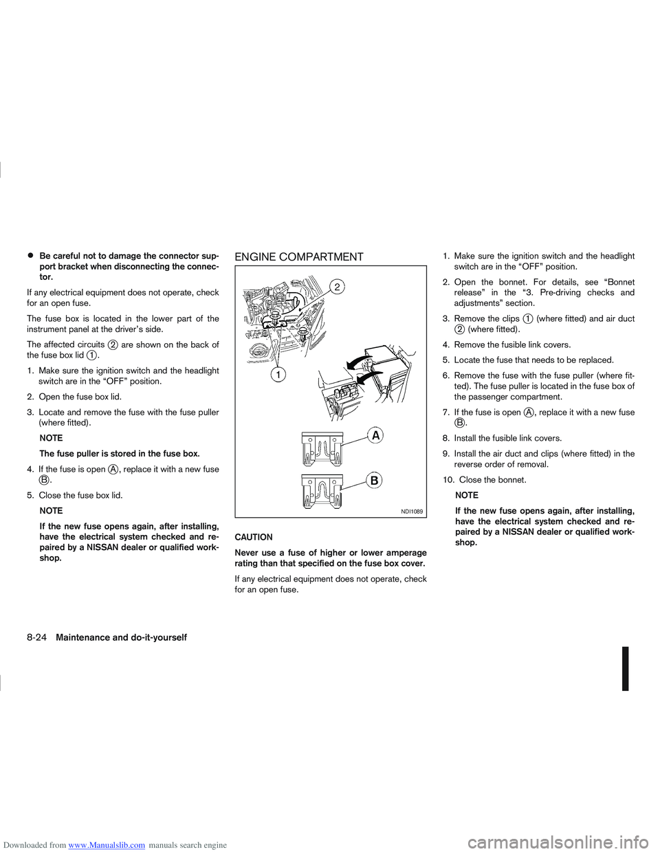
for an open fuse. 1. Make sure the ignition switch and the headlight
switch are in the “OFF” position.
2. Open the bonnet. For details, see “Bonnet release” in the “3. Pre-driving checks and
adjustments” section.
3. Remove the clips
j1 (where fitted) and air ductj2 (where fitted).
4. Remove the fusible link covers.
5. Locate the fuse that needs to be replaced.
6. Remove the fuse with the fuse puller (where fit- ted). The fuse puller is located in the fuse box of
the passenger compartment.
7. If the fuse is open
jA , replace it with a new fusejB.
8. Install the fusible link covers.
9. Install the air duct and clips (where fitted) in the reverse order of removal.
10. Close the bonnet. NOTE
If the new fuse opens again, after installing,
have the electrical system checked and re-
paired by a NISSAN dealer or qualified work-
shop.
NDI1089
8-24Maintenance and do-it-yourself
Page 257 of 297

Downloaded from www.Manualslib.com manuals search engine Only hold the xenon headlight bulb by the
base.
The bulb is manufactured from high-quality
quartz and is under high pressure.
Damage, soiling, and fingerprints should be
avoided and, if necessary, removed with alco-
hol before installing the bulb.
When the headlights are switched on, the
bulbs produce a certain amount of UV radia-
tion. In order to avoid any impairment of health
(burning and conjunctivitis), the bulb should
only be used in closed headlights with appro-
priate UV–absorbing front glass.
Due to the risk of burning, the bulb should be
left to cool down for 3 minutes after switching
off before touching.
Due to the use of mercury and various salts,
the bulb should be treated as special waste
when discarded.
The bulb may only be operated with a suitable
ballast which produces very high voltages
when switched on and during operation.
Contact with bulb and wires should therefore
be avoided and a safe distance of at least 30
mm should be maintained.
Replacing the halogen headlight bulb
CAUTION
High pressure halogen gas is sealed inside
the halogen bulb. The bulb may break if the
glass envelope is scratched or the bulb is
dropped.
When handling the bulb, DO NOT TOUCH THE
GLASS ENVELOPE.
Use the same number type and wattage as
originally installed.
Aiming is usually not necessary after replac-
ing the bulb. When aiming adjustment is nec-
essary, contact a NISSAN dealer or qualified
workshop.
Do not leave the bulb out of the headlight
reflector for a long period of time as dust,
moisture or smoke may enter the headlight
body and affect the performance of the head-
light.
The headlight is a semi-sealed beam type which
uses a replaceable headlight (halogen) bulb. A bulb
can be replaced from inside the engine compart-
ment without removing the headlight assembly.
Contact a NISSAN dealer or qualified workshop, if
you need assistance for bulb replacement.
1. Open the bonnet. For details, see “Bonnet release” in the “3. Pre-driving checks and
adjustments” section.
2. Disconnect the negative (—) battery cable. 3. When the broken bulb is located in the headlight
assembly under the air duct, carefully remove the
clips and rotate the air duct
jc clockwise a 1/4
of a turn.
4. Remove the cap (
jAorjB ) of the headlight as-
sembly.
5. Turn the connector 1/4 of a turn in the anti clock- wise direction and remove the headlight bulb.
6. Install the new bulb in the reverse order of re- moval and make sure that the cap is securely
sealed with the headlight body.
7. Where removed (step 3.), re-install the air duct
jc and clips in the order of removal.
8. Reconnect the negative (—) battery cable and close the bonnet.
NOTE
Fog may temporarily form inside the lens of the
exterior lights in the rain or in a car wash. The fog
is caused by a temperature difference between
the inside and the outside of the lens. This is not
a malfunction. If large droplets can be seen, then
contact a NISSAN dealer or qualified workshop.
8-26Maintenance and do-it-yourself
Page 258 of 297
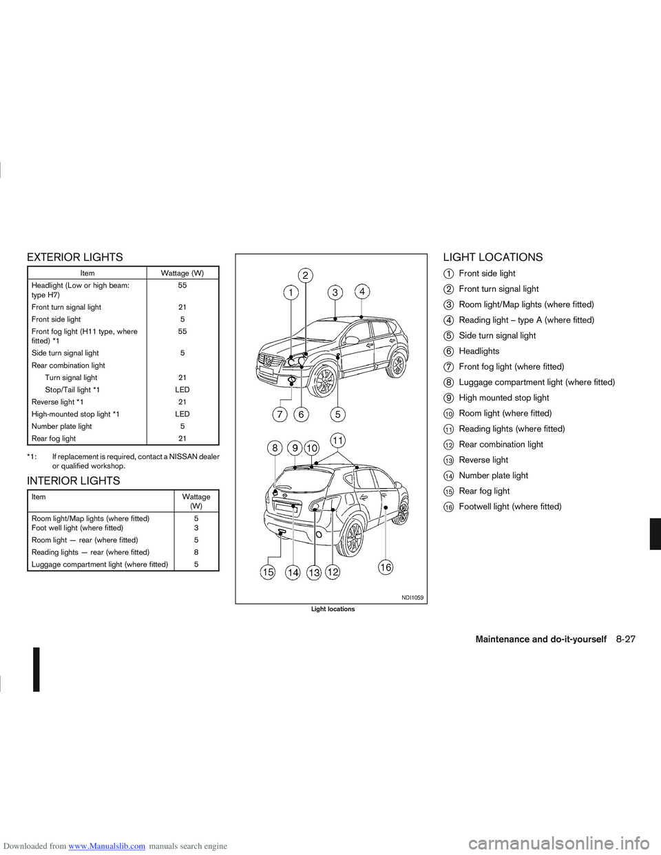
Downloaded from www.Manualslib.com manuals search engine EXTERIOR LIGHTS
ItemWattage (W)
Headlight (Low or high beam:
type H7) 55
Front turn signal light 21
Front side light 5
Front fog light (H11 type, where
fitted) *1 55
Side turn signal light 5
Rear combination light Turn signal light 21
Stop/Tail light *1 LED
Reverse light *1 21
High-mounted stop light *1 LED
Number plate light 5
Rear fog light 21
*1: If replacement is required, contact a NISSAN dealer or qualified workshop.
INTERIOR LIGHTS
Item Wattage
(W)
Room light/Map lights (where fitted)
Foot well light (where fitted) 5
3
Room light — rear (where fitted) 5
Reading lights — rear (where fitted) 8
Luggage compartment light (where fitted) 5
LIGHT LOCATIONS
j
1 Front side light
j2Front turn signal light
j3Room light/Map lights (where fitted)
j4Reading light – type A (where fitted)
j5Side turn signal light
j6Headlights
j7Front fog light (where fitted)
j8Luggage compartment light (where fitted)
j9High mounted stop light
j10Room light (where fitted)
j11Reading lights (where fitted)
j12Rear combination light
j13Reverse light
j14Number plate light
j15Rear fog light
j16Footwell light (where fitted)
NDI1059
Light locations
Maintenance and do-it-yourself8-27