2012 NISSAN QASHQAI instrument panel
[x] Cancel search: instrument panelPage 84 of 297

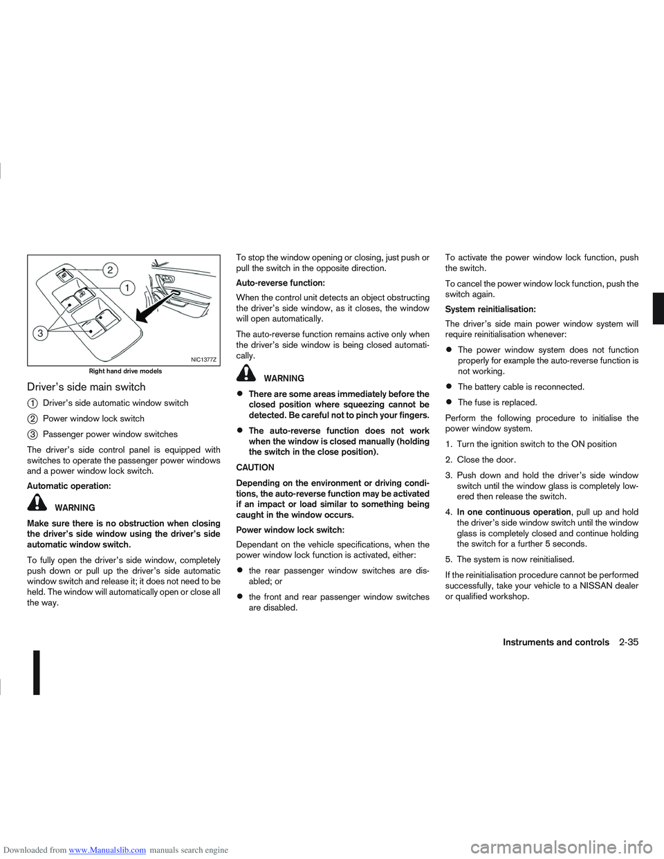
Downloaded from www.Manualslib.com manuals search engine Driver’s side main switch
j
1Driver’s side automatic window switch
j2Power window lock switch
j3Passenger power window switches
The driver’s side control panel is equipped with
switches to operate the passenger power windows
and a power window lock switch.
Automatic operation:
WARNING
Make sure there is no obstruction when closing
the driver’s side window using the driver’s side
automatic window switch.
To fully open the driver’s side window, completely
push down or pull up the driver’s side automatic
window switch and release it; it does not need to be
held. The window will automatically open or close all
the way. To stop the window opening or closing, just push or
pull the switch in the opposite direction.
Auto-reverse function:
When the control unit detects an object obstructing
the driver’s side window, as it closes, the window
will open automatically.
The auto-reverse function remains active only when
the driver’s side window is being closed automati-
cally.
WARNING
There are some areas immediately before the
closed position where squeezing cannot be
detected. Be careful not to pinch your fingers.
The auto-reverse function does not work
when the window is closed manually (holding
the switch in the close position).
CAUTION
Depending on the environment or driving condi-
tions, the auto-reverse function may be activated
if an impact or load similar to something being
caught in the window occurs.
Power window lock switch:
Dependant on the vehicle specifications, when the
power window lock function is activated, either:
the rear passenger window switches are dis-
abled; or
the front and rear passenger window switches
are disabled. To activate the power window lock function, push
the switch.
To cancel the power window lock function, push the
switch again.
System reinitialisation:
The driver’s side main power window system will
require reinitialisation whenever:
The power window system does not function
properly for example the auto-reverse function is
not working.
The battery cable is reconnected.
The fuse is replaced.
Perform the following procedure to initialise the
power window system.
1. Turn the ignition switch to the ON position
2. Close the door.
3. Push down and hold the driver’s side window switch until the window glass is completely low-
ered then release the switch.
4. In one continuous operation , pull up and hold
the driver’s side window switch until the window
glass is completely closed and continue holding
the switch for a further 5 seconds.
5. The system is now reinitialised.
If the reinitialisation procedure cannot be performed
successfully, take your vehicle to a NISSAN dealer
or qualified workshop.
NIC1377Z
Right hand drive models
Instruments and controls2-35
Page 102 of 297

Downloaded from www.Manualslib.com manuals search engine jALHD models
jB RHD models
1. Pull the bonnet lock release lever
j1 , located
below the instrument panel on the driver’s side;
the bonnet will spring up slightly.
2. Slide the lever
j2 , at the front of the bonnet, with
your fingertips and raise the bonnet.
3. Insert the support rod
j3 into the slot on the
underside of the bonnet.
4. When closing the bonnet, replace the support rod in its original position, then slowly close the
bonnet and make sure it locks into place.
WARNING
Always check whether the bonnet is closed and
locked securely to prevent it from opening while
driving. The vehicle should only be operated with
the bonnet securely closed.
FUEL FILLER LID OPENER LEVER
j
A LHD models
jB RHD models
To open the fuel filler lid, pull up the opener lever,
located below the instrument panel on the driver’s
side. To lock, close the fuel filler lid securely.
FUEL FILLER CAP
The fuel filler cap is a ratcheting type. Tighten the
cap clockwise until ratcheting clicks are heard.
Put the fuel filler cap on the cap holder as illustrated
while refuelling.
WARNING
Fuel is extremely flammable and highly explo-
sive under certain conditions. Always stop the
engine and do not smoke or allow open flames
or sparks near the vehicle when refuelling.
Fuel may be under pressure. Turn the cap half
a turn and wait for any hissing sound to stop,
in order to prevent fuel from spraying out and
causing possible personal injury.
Use only a NISSAN fuel filler cap or exact
equivalent as a replacement. It has a built-in
safety valve needed for proper operation of
NPA1004NPA832Z
FUEL FILLER LID
Pre-driving checks and adjustments3-15
Page 203 of 297

Downloaded from www.Manualslib.com manuals search engine and varies the brake fluid pressure to prevent each
wheel from locking and sliding. By preventing each
wheel from locking, the system helps the driver to
maintain steering control and helps to minimise
swerving and spinning on slippery surfaces.
Using the system
Depress the brake pedal and hold it down. Depress
the brake pedal with firm steady pressure, but do
not pump the brakes. The ABS will operate to pre-
vent the wheels from locking up. Steer the vehicle to
avoid obstacles.
WARNING
Do not pump the brake pedal. Doing so may in-
crease the stopping distance.
Self-test feature
The ABS includes electronic sensors, electric
pumps, hydraulic solenoids and a computer. The
computer has a built-in diagnostic feature that tests
the system each time you start the engine and move
thevehicleatalowspeedinforwardorreverse.
When the self-test occurs, you may hear a “clunk”
noise and/or feel a pulsation in the brake pedal. This
is normal and does not indicate a malfunction. If the
computer senses a malfunction, it switches the ABS
off and illuminates the ABS warning light on the
instrument panel. The brake system then operates
normally, but without anti-lock assistance.
If the ABS warning light illuminates during the self-
test or while driving, have the vehicle checked by a
NISSAN dealer or qualified workshop.
Normal operation
The ABS will not initiate at speeds below 5 to 10
km/h (3 to 6 MPH). The speeds will vary according
to road conditions.
When the ABS senses that one or more wheels are
close to locking up, the actuator rapidly applies and
releases hydraulic pressure. This action is similar to
pumping the brakes very quickly. You may feel a
pulsation in the brake pedal and hear a noise from
the actuator under the bonnet when it is operating.
This is normal and indicates that the ABS is working
properly. However, the pulsation may indicate that
road conditions are hazardous and extra care is re-
quired while driving. When accelerating, driving on slippery surfaces or
suddenly avoiding obstacles on roads, the vehicle
might swerve or slip. The Electronic Stability Pro-
gramme (ESP) system continuously monitors and
compares the driver’s intended speed and the travel
direction. The system adjusts wheel brake pressure
and engine torque to assist in improving vehicle sta-
bility.
When the ESP system is operating, the “SLIP”
indicator light () in the combination meter
blinks.
When only the traction control (TCS) system in
the ESP system is operating, the “SLIP” indica-
tor light (
) in the combination meter will also
blink.
If the “SLIP” indicator light () blinks, the
road conditions are slippery. Be sure to drive
carefully. See “Warning/indicator lights and au-
dible reminders” in the “2. Instruments and
controls” section.
Indicator light
If a malfunction occurs in the system, the “SLIP”
indicator light (
) and the ESP indicator light
() come on in the combination meter.
As long as these indicator lights are on, the trac-
tion control function is cancelled.
The ESP system uses Active Brake Limited Slip
(ABLS) system to improve vehicle traction. The Ac-
tive Brake Limited Slip (ABLS) system works when
one of the driving wheels is spinning on a slippery
ELECTRONIC STABILITY
PROGRAMME (ESP) SYSTEM
(where fitted)
5-40Starting and driving
Page 255 of 297

Downloaded from www.Manualslib.com manuals search engine Be careful not to damage the connector sup-
port bracket when disconnecting the connec-
tor.
If any electrical equipment does not operate, check
for an open fuse.
The fuse box is located in the lower part of the
instrument panel at the driver’s side.
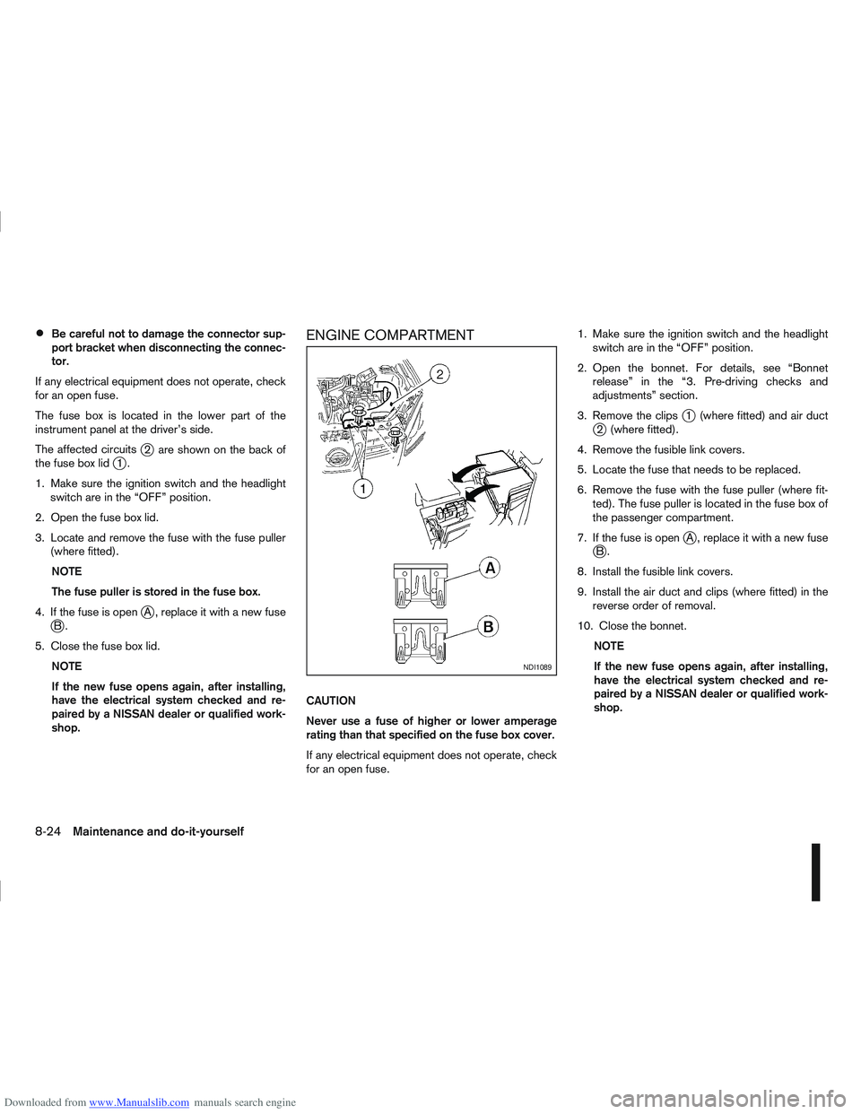
The affected circuits
j2 are shown on the back of
the fuse box lidj1.
1. Make sure the ignition switch and the headlight switch are in the “OFF” position.
2. Open the fuse box lid.
3. Locate and remove the fuse with the fuse puller (where fitted).
NOTE
The fuse puller is stored in the fuse box.
4. If the fuse is open
jA , replace it with a new fusejB.
5. Close the fuse box lid. NOTE
If the new fuse opens again, after installing,
have the electrical system checked and re-
paired by a NISSAN dealer or qualified work-
shop.
ENGINE COMPARTMENT
CAUTION
Never use a fuse of higher or lower amperage
rating than that specified on the fuse box cover.
If any electrical equipment does not operate, check
for an open fuse. 1. Make sure the ignition switch and the headlight
switch are in the “OFF” position.
2. Open the bonnet. For details, see “Bonnet release” in the “3. Pre-driving checks and
adjustments” section.
3. Remove the clips
j1 (where fitted) and air ductj2 (where fitted).
4. Remove the fusible link covers.
5. Locate the fuse that needs to be replaced.
6. Remove the fuse with the fuse puller (where fit- ted). The fuse puller is located in the fuse box of
the passenger compartment.
7. If the fuse is open
jA , replace it with a new fusejB.
8. Install the fusible link covers.
9. Install the air duct and clips (where fitted) in the reverse order of removal.
10. Close the bonnet. NOTE
If the new fuse opens again, after installing,
have the electrical system checked and re-
paired by a NISSAN dealer or qualified work-
shop.
NDI1089
8-24Maintenance and do-it-yourself