2012 NISSAN CUBE ECO mode
[x] Cancel search: ECO modePage 30 of 331
1-12Safety — Seats, seat belts and supplemental restraint system
.Once a seat belt pretensioner has
activated, it cannot be reused and
must be replaced together with the
retractor. See a NISSAN dealer.
. Removal and installation of the
pretensioner system components
should be done by a NISSAN dealer.
. All seat belt assemblies, including
retractors and attaching hardware,
should be inspected after any colli-
sion by a NISSAN dealer. NISSAN
recommends that all seat belt as-
semblies in use during a collision be
replaced unless the collision was
minor and the belts show no da-
mage and continue to operate prop-
erly. Seat belt assemblies not in use
during a collision should also be
inspected and replaced if either
damage or improper operation is
noted.
. All child restraints and attaching
hardware should be inspected after
any collision. Always follow the
restraint manufacturer’s inspection
instructions and replacement re-
commendations. The child restraints
should be replaced if they are damaged.
PREGNANT WOMEN
NISSAN recommends that pregnant women use
seat belts. The seat belt should be worn snug,
and always position the lap belt as low as
possible around the hips, not the waist. Place
the shoulder belt over your shoulder and across
your chest. Never put the lap/shoulder belt over
your abdominal area. Contact your doctor for
specific recommendations.
INJURED PERSONS
NISSAN recommends that injured persons use
seat belts, depending on the injury. Check with
your doctor for specific recommendations.
THREE-POINT TYPE SEAT BELT
WARNING
.
Every person who drives or rides in
this vehicle should use a seat belt at
all times.
. Do not ride in a moving vehicle
when the seatback is reclined. This
can be dangerous. The shoulder belt
will not be against your body. In an
accident, you could be thrown into it
and receive neck or other serious injuries. You could also slide under
the lap belt and receive serious
internal injuries.
. For the most effective protection
when the vehicle is in motion, the
seat should be upright. Always sit
well back in the seat with both feet
on the floor and adjust the seat belt
properly.
. Do not allow children to play with
the seat belts. Most seating posi-
tions are equipped with Automatic
Locking Retractor (ALR) mode seat
belts. If the seat belt becomes
wrapped around a child’s neck with
the ALR mode activated, the child
can be seriously injured or killed if
the seat belt retracts and becomes
tight. This can occur even if the
vehicle is parked. Unbuckle the seat
belt to release the child. For the
center of the rear seat, the connec-
tor tongue may also be released.
Release the connector tongue by
inserting a suitable tool (such as a
key) into the connector buckle. If the
seat belt can not be unbuckled or is
already unbuckled, release the child
by cutting the seat belt with a
Page 37 of 331
collision or a sudden stop.
SEAT BELT MAINTENANCE
.To clean the seat belt webbing, apply a
mild soap solution or any solution recom-
mended for cleaning upholstery or carpets.
Then wipe with a cloth and allow the seat
belts to dry in the shade. Do not allow the
seat belts to retract until they are completely
dry.
. If dirt builds up in the shoulder belt
guide of the seat belt anchors, the seat
belts may retract slowly. Wipe the shoulder
belt guide with a clean, dry cloth.
. Periodically check to see that the seat
belt and the metal components, such as
buckles, tongues, retractors, flexible wires
and anchors, work properly. If loose parts,
deterioration, cuts or other damage on the
webbing is found, the entire seat belt
assembly should be replaced.
WARNING
Do not allow children to play with the
seat belts. Most seating positions are
equipped with Automatic Locking Re-
tractor (ALR) mode seat belts. If the
seat belt becomes wrapped around a
child’s neck with the ALR mode acti-
vated, the child can be seriously injured
or killed if the seat belt retracts and
becomes tight. This can occur even if
the vehicle is parked. Unbuckle the seat
belt to release the child. For the center
of the rear seat, the connector tongue
may also be released. Release the
connector tongue by inserting a suita-
ble tool (such as a key) into the
connector buckle. If the seat belt can
not be unbuckled or is already un-
buckled, release the child by cutting
the seat belt with a suitable tool (such
as a knife or scissors) to release the
seat belt.
Children need adults to help protect them.
They need to be properly restrained.
In addition to the general information in this
manual, child safety information is available from many other sources, including doctors, teachers,
government traffic safety offices, and community
organizations. Every child is different, so be sure
to learn the best way to transport your child.
There are three basic types of child restraint
systems:
.
Rear-facing child restraint
. Forward-facing child restraint
. Booster seat
The proper restraint depends on the child’s size.
Generally, infants up to about 1 year and less
than 20 lbs (9 kg) should be placed in rear-
facing child restraints. Forward-facing child
restraints are available for children who outgrow
rear-facing child restraints and are at least 1
year old. Booster seats are used to help position
a vehicle lap/shoulder belt on a child who can no
longer use a forward-facing child restraint.
WARNING
Infants and children need special pro-
tection. The vehicle’s seat belts may not
fit them properly. The shoulder belt may
come too close to the face or neck. The
lap belt may not fit over their small hip
bones. In an accident, an improperly
fitting seat belt could cause serious or
fatal injury. Always use appropriate
Safety — Seats, seat belts and supplemental restraint system1-19
CHILD SAFETY
Page 66 of 331

1-48Safety — Seats, seat belts and supplemental restraint system
below as permitted by U.S. regulations. If the
front passenger air bag is OFF, it will not inflate
in a crash. The driver air bag and other air bags
in your vehicle are not part of this system.
The purpose of the regulation is to help reduce
the risk of injury or death from an inflating air bag
to certain front passenger seat occupants, such
as children, by requiring the air bag to be
automatically turned OFF.
The occupant classification sensors (weight
sensors) are on the seat cushion frame under
the front passenger seat and are designed to
detect an occupant and objects on the seat. For
example, if a child is in the front passenger seat,
the Advanced Air Bag System is designed to
turn the passenger air bag OFF in accordance
with the regulations. Also, if a child restraint of
the type specified in the regulations is on the
seat, the occupant classification sensors can
detect it and cause the air bag to turn OFF.
Front passenger seat adult occupants who are
properly seated and using the seat belt as
outlined in this manual should not cause the
passenger air bag to be automatically turned
OFF. For small adults it may be turned OFF,
however, if the occupant does not sit in the seat
properly (for example, by not sitting upright, by
sitting on an edge of the seat, or by otherwise
being out of position) , this could cause thesensors to turn the air bag OFF. Always be sure
to be seated and wearing the seat belt properly
for the most effective protection by the seat belt
and supplemental air bag.
NISSAN recommends that pre-teens and chil-
dren be properly restrained in a rear seat.
NISSAN also recommends that appropriate
child restraints and booster seats be properly
installed in a rear seat. If this is not possible, the
occupant classification sensors are designed to
operate as described above to turn the front
passenger air bag OFF for specified child
restraints. Failing to properly secure child
restrains and to use the Automatic Locking
Retractor (ALR) mode (child restraint mode)
may allow the restraint to tip or move in an
accident or sudden stop. This can also result in
the passenger air bag inflating in a crash instead
of being OFF. (See “Child restraints” (P.1-21)
for proper use and installation.)
If the front passenger seat is not occupied, the
passenger air bag is designed not to inflate in a
crash. However, heavy objects placed on the
seat could result in air bag inflation, because of
the object being detected by the occupant
classification sensors. Other conditions could
also result in air bag inflation, such as if a child is
standing on the seat, or if two children are on the
seat, contrary to the instructions in this manual.
Always be sure that you and all vehicleoccupants are seated and restrained properly.
Using the passenger air bag status light, you can
monitor when the front passenger air bag is
automatically turned OFF with the seat occu-
pied. The light will not illuminate when the front
passenger seat is unoccupied.
If an adult occupant is in the seat but the
passenger air bag status light is illuminated
(indicating that the air bag is OFF) , it could be
that the person is a small adult, or is not sitting
on the seat properly.
If a child restraint must be used in the front seat,
the passenger air bag status light may or may
not be illuminated, depending on the size of the
child and the type of child restraint being used. If
the air bag status light is not illuminated
(indicating that the air bag might inflate in a
crash) , it could be that the child restraint or seat
belt is not being used properly. Make sure that
the child restraint is installed properly, the seat
belt is used properly and the occupant is
positioned properly. If the air bag status light is
not illuminated, reposition the occupant or child
restraint in a rear seat.
If the passenger air bag status light will not
illuminate even though you believe that the child
restraint, the seat belts and the occupant are
properly positioned, the system may be sensing
an unoccupied seat (in which case the air bag is
Page 77 of 331
SIC4120
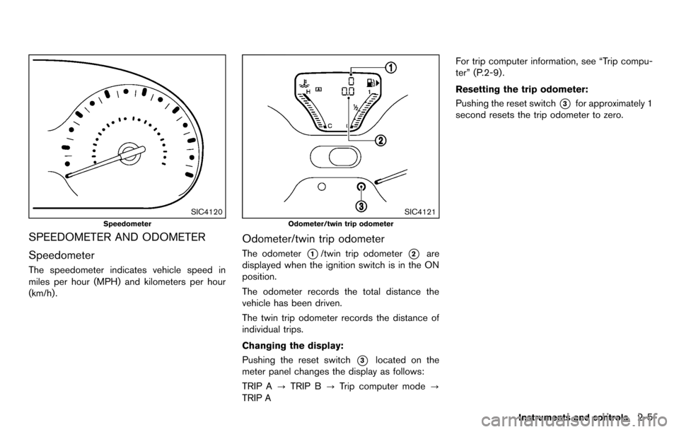
Speedometer
SPEEDOMETER AND ODOMETER
Speedometer
The speedometer indicates vehicle speed in
miles per hour (MPH) and kilometers per hour
(km/h) .
SIC4121
Odometer/twin trip odometer
Odometer/twin trip odometer
The odometer*1/twin trip odometer*2are
displayed when the ignition switch is in the ON
position.
The odometer records the total distance the
vehicle has been driven.
The twin trip odometer records the distance of
individual trips.
Changing the display:
Pushing the reset switch
*3located on the
meter panel changes the display as follows:
TRIP A ?TRIP B ?Trip computer mode ?
TRIP A For trip computer information, see “Trip compu-
ter” (P.2-9) .
Resetting the trip odometer:
Pushing the reset switch
*3for approximately 1
second resets the trip odometer to zero.
Instruments and controls2-5
Page 78 of 331
2-6Instruments and controls
SIC4712
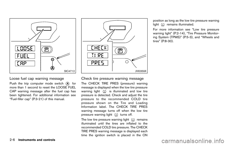
Loose fuel cap warning message
Push the trip computer mode switch*Afor
more than 1 second to reset the LOOSE FUEL
CAP warning message after the fuel cap has
been tightened. For additional information see
“Fuel-filler cap” (P.3-21) of this manual.
JVI0359X
Check tire pressure warning message
The CHECK TIRE PRES (pressure) warning
message is displayed when the low tire pressure
warning light
is illuminated and low tire
pressure is detected. Check and adjust the tire
pressure to the recommended COLD tire
pressure shown on the Tire and Loading
Information label. The CHECK TIRE PRES
warning message turns off when the low tire
pressure warning light
turns off.
The low tire pressure warning light
remains
illuminated until the tires are inflated to the
recommended COLD tire pressure. The CHECK
TIRE PRES warning message is displayed each
time the ignition switch is placed in the ON position as long as the low tire pressure warning
light
remains illuminated.
For more information see “Low tire pressure
warning light” (P.2-14) , “Tire Pressure Monitor-
ing System (TPMS)” (P.5-3) , and “Wheels and
tires” (P.8-30).
Page 81 of 331
OUTSIDE AIR TEMPERATURE (if so
equipped)
The outside air temperature is displayed in8For
8C.
When the outside air temperature becomes
378F(3 8C) or lower, the outside air temperature
display blinks to give a warning. The display will
stop blinking after 1 minute or when the outside
air temperature becomes 398F(4 8C) or above.
The display may differ from the actual outside
temperature displayed on various signs or bill-
boards.
CONTINUOUSLY VARIABLE TRANS-
MISSION (CVT) POSITION INDICATOR
(if so equipped)
The Continuously Variable Transmission (CVT)
position indicator indicates the selector lever
position when the ignition switch is in the ON
position.
SIC4126
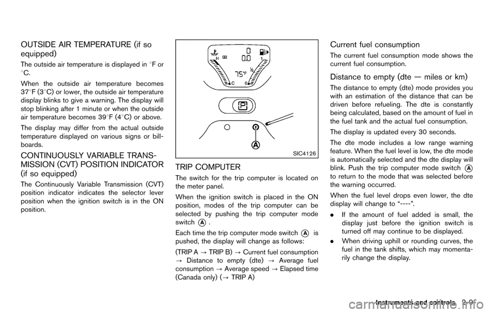
TRIP COMPUTER
The switch for the trip computer is located on
the meter panel.
When the ignition switch is placed in the ON
position, modes of the trip computer can be
selected by pushing the trip computer mode
switch
*A.
Each time the trip computer mode switch
*Ais
pushed, the display will change as follows:
(TRIP A ?TRIP B) ?Current fuel consumption
? Distance to empty (dte) ?Average fuel
consumption ?Average speed ?Elapsed time
(Canada only) (? TRIP A)
Current fuel consumption
The current fuel consumption mode shows the
current fuel consumption.
Distance to empty (dte — miles or km)
The distance to empty (dte) mode provides you
with an estimation of the distance that can be
driven before refueling. The dte is constantly
being calculated, based on the amount of fuel in
the fuel tank and the actual fuel consumption.
The display is updated every 30 seconds.
The dte mode includes a low range warning
feature. When the fuel level is low, the dte mode
is automatically selected and the dte display will
blink. Push the trip computer mode switch
*A
to return to the mode that was selected before
the warning occurred.
When the fuel level drops even lower, the dte
display will change to “----”.
.If the amount of fuel added is small, the
display just before the ignition switch is
turned off may continue to be displayed.
. When driving uphill or rounding curves, the
fuel in the tank shifts, which may momenta-
rily change the display.
Instruments and controls2-9
Page 82 of 331
2-10Instruments and controls
Average fuel consumption (mpg or l
(liter)/100 km)
The average fuel consumption mode shows the
average fuel consumption since the last reset.
Resetting is done by pushing the trip computer
mode switch
*Afor approximately 1 second.
The display is updated every 30 seconds. At
about the first 1/3 mile (500 m) after a reset, the
display shows “---”.
Average speed (mph or km/h)
The average speed mode shows the average
vehicle speed since the last reset. Resetting is
done by pushing the trip computer mode switch
*Afor approximately 1 second.
The display is updated every 30 seconds. The
first 30 seconds after a reset, the display shows
“---”.
Elapsed time (Canada only)
The elapsed time mode shows the time since
the last reset. The displayed time can be reset
by pushing the trip computer mode switch
*A
for approximately 1 second.
Resetting displays
When the average fuel consumption, average
speed, elapsed time or TRIP B is displayed,
push the trip computer mode switch
*Afor
longer than 3 seconds. The average fuel
consumption, average speed, elapsed time and
trip odometer (TRIP B only) displays will be reset
at the same time.
Maintenance information (Canada only)
When the ignition switch is placed in the ON
position, maintenance information (the wrench
symbol
and distance to change a main-
tenance item) comes on for about 5 seconds
and then turns off.
The wrench symbol
appears when the set
distance comes for changing an item, such as
engine oil.
To set the distance to change an item:
1. Place the ignition switch in the ON position.
Push the trip computer mode switch
*Afor
3 seconds while the wrench symbol
and maintenance information are displayed.
The symbol and distance display will start
flashing and the display shows the current
interval.
2. Push the switch
*Ato increase the interval
distance. Each step increases the interval distance by
500 miles (1,000 km) . The interval distance
can be set up to 18,000 miles (30,000 km)
after the display returns to 0 (zero).
3. If no further action is made, the display returns to the previous mode and the new
interval is set.
If the interval distance is set to 0, the display will
skip the maintenance information when the
ignition switch is placed in the ON position.
Page 89 of 331
High beam indicator light
This light illuminates when the headlight high
beam is on and goes out when the low beam is
selected.
Malfunction Indicator Light (MIL)
If the malfunction indicator light illuminates
steady or blinks while the engine is running, it
may indicate a potential emission control and/or
Continuously Variable Transmission (CVT) mal-
function.
The malfunction indicator light may also illumi-
nate steady if the fuel-filler cap is loose or
missing, or if the vehicle runs out of fuel. Check
to make sure the fuel-filler cap is installed and
closed tightly, and that the vehicle has at least 3
US gallons (11.4 liters) of fuel in the fuel tank.
After a few driving trips, the
light should
turn off if no other potential emission control
system malfunction exists.
If this indicator light remains on for 20 seconds
and then blinks for 10 seconds when the engine
is not running, it indicates that the vehicle is not
ready for an emission control system inspection/
maintenance test. (See “Readiness for Inspec-
tion/Maintenance (I/M) test” (P.9-19) .)
Operation:
The malfunction indicator light will illuminate in
one of two ways: .
Malfunction indicator light illuminated steady
— An emission control system and/or CVT
malfunction has been detected. Check the
fuel-filler cap if the LOOSE FUEL CAP
warning message is displayed on the twin
trip odometer. If the fuel-filler cap is loose or
missing, tighten or install the cap and
continue to drive the vehicle. The
light
should turn off after a few driving trips. If the
light does not turn off after a few driving
trips, have the vehicle inspected by a
NISSAN dealer. You do not need to have
your vehicle towed to the dealer.
. Malfunction indicator light blinking — An
engine misfire has been detected which may
damage the emission control system.
To reduce or avoid emission control system
damage:
1) Do not drive at speeds above 45 MPH
(72 km/h).
2) Avoid hard acceleration or deceleration.
3) Avoid steep uphill grades.
4) If possible, reduce the amount of cargo being hauled or towed.
The malfunction indicator light may stop
blinking and remain illuminated.
Have the vehicle inspected by a NISSAN
dealer. You do not need to have your vehicle
towed to the dealer.
CAUTION
Continued vehicle operation without
having the emission control system
and/or CVT system checked and re-
paired as necessary could lead to poor
driveability, reduced fuel economy, and
possible damage to the emission con-
trol system.
Overdrive off indicator light (if so
equipped)
The overdrive off indicator light illuminates when
the overdrive off mode is selected.
For additional information, see “Continuously
Variable Transmission (CVT)” (P.5-14) of this
manual.
Security indicator light
The light blinks when the ignition switch is in the
ACC, OFF or LOCK position. This function
indicates the security system equipped on the
vehicle is operational.
If the security system is malfunctioning, this light
will remain on while the ignition switch is in the
ON position. For additional information, see
“Security systems” (P.2-19) .
Instruments and controls2-17