2012 NISSAN CUBE spare tire
[x] Cancel search: spare tirePage 294 of 331
8-32Maintenance and do-it-yourself
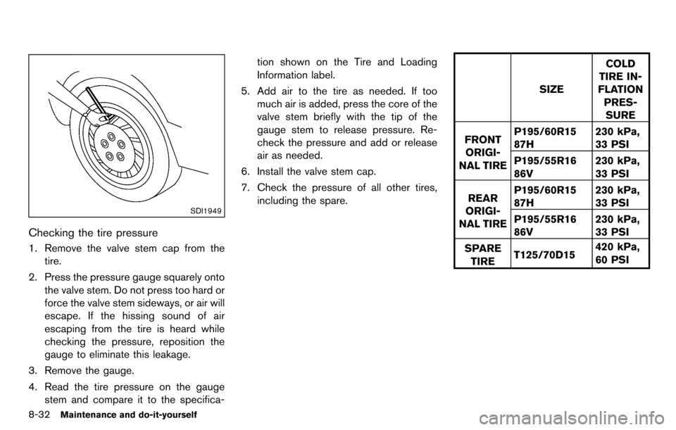
SDI1949
Checking the tire pressure
1. Remove the valve stem cap from thetire.
2. Press the pressure gauge squarely onto the valve stem. Do not press too hard or
force the valve stem sideways, or air will
escape. If the hissing sound of air
escaping from the tire is heard while
checking the pressure, reposition the
gauge to eliminate this leakage.
3. Remove the gauge.
4. Read the tire pressure on the gauge stem and compare it to the specifica- tion shown on the Tire and Loading
Information label.
5. Add air to the tire as needed. If too much air is added, press the core of the
valve stem briefly with the tip of the
gauge stem to release pressure. Re-
check the pressure and add or release
air as needed.
6. Install the valve stem cap.
7. Check the pressure of all other tires, including the spare.
SIZE COLD
TIRE IN-
FLATION
PRES-SURE
FRONT ORIGI-
NAL TIRE P195/60R15
87H
230 kPa,
33 PSI
P195/55R16
86V 230 kPa,
33 PSI
REAR
ORIGI-
NAL TIRE P195/60R15
87H
230 kPa,
33 PSI
P195/55R16
86V 230 kPa,
33 PSI
SPARE TIRE T125/70D15 420 kPa,
60 PSI
Page 298 of 331
8-36Maintenance and do-it-yourself
clearances are determined using the factory
equipped tire size. Other types may damage
your vehicle. Use chain tensioners when re-
commended by the tire chain manufacturer to
ensure a tight fit. Loose end links of the tire
chain must be secured or removed to prevent
the possibility of whipping action damage to the
fenders or underbody. If possible, avoid fully
loading your vehicle when using tire chains. In
addition, drive at a reduced speed. Otherwise,
your vehicle may be damaged and/or vehicle
handling and performance may be adversely
affected.
Tire chains must be installed only on the
front wheels and not on the rear wheels.
Never install tire chains on a TEMPORARY USE
ONLY spare tire.
Do not use tire chains on dry roads. Driving with
tire chains in such conditions can cause damage
to the various mechanisms of the vehicle due to
some overstress.
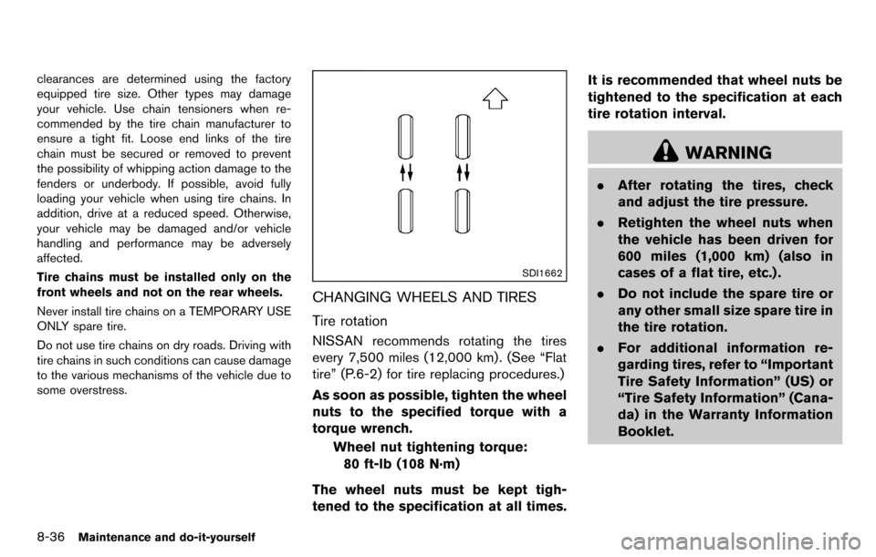
SDI1662
CHANGING WHEELS AND TIRES
Tire rotation
NISSAN recommends rotating the tires
every 7,500 miles (12,000 km) . (See “Flat
tire” (P.6-2) for tire replacing procedures.)
As soon as possible, tighten the wheel
nuts to the specified torque with a
torque wrench.Wheel nut tightening torque:80 ft-lb (108 N·m)
The wheel nuts must be kept tigh-
tened to the specification at all times. It is recommended that wheel nuts be
tightened to the specification at each
tire rotation interval.
WARNING
.
After rotating the tires, check
and adjust the tire pressure.
. Retighten the wheel nuts when
the vehicle has been driven for
600 miles (1,000 km) (also in
cases of a flat tire, etc.) .
. Do not include the spare tire or
any other small size spare tire in
the tire rotation.
. For additional information re-
garding tires, refer to “Important
Tire Safety Information” (US) or
“Tire Safety Information” (Cana-
da) in the Warranty Information
Booklet.
Page 299 of 331
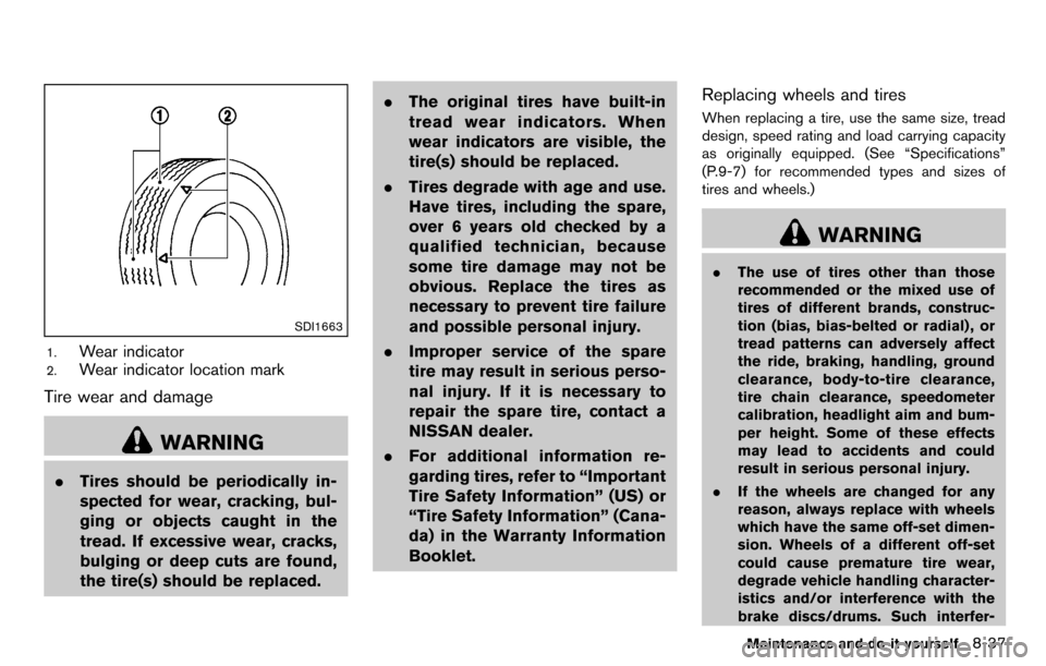
SDI1663
1.Wear indicator
2.Wear indicator location mark
Tire wear and damage
WARNING
.Tires should be periodically in-
spected for wear, cracking, bul-
ging or objects caught in the
tread. If excessive wear, cracks,
bulging or deep cuts are found,
the tire(s) should be replaced. .
The original tires have built-in
tread wear indicators. When
wear indicators are visible, the
tire(s) should be replaced.
. Tires degrade with age and use.
Have tires, including the spare,
over 6 years old checked by a
qualified technician, because
some tire damage may not be
obvious. Replace the tires as
necessary to prevent tire failure
and possible personal injury.
. Improper service of the spare
tire may result in serious perso-
nal injury. If it is necessary to
repair the spare tire, contact a
NISSAN dealer.
. For additional information re-
garding tires, refer to “Important
Tire Safety Information” (US) or
“Tire Safety Information” (Cana-
da) in the Warranty Information
Booklet.
Replacing wheels and tires
When replacing a tire, use the same size, tread
design, speed rating and load carrying capacity
as originally equipped. (See “Specifications”
(P.9-7) for recommended types and sizes of
tires and wheels.)
WARNING
. The use of tires other than those
recommended or the mixed use of
tires of different brands, construc-
tion (bias, bias-belted or radial) , or
tread patterns can adversely affect
the ride, braking, handling, ground
clearance, body-to-tire clearance,
tire chain clearance, speedometer
calibration, headlight aim and bum-
per height. Some of these effects
may lead to accidents and could
result in serious personal injury.
. If the wheels are changed for any
reason, always replace with wheels
which have the same off-set dimen-
sion. Wheels of a different off-set
could cause premature tire wear,
degrade vehicle handling character-
istics and/or interference with the
brake discs/drums. Such interfer-
Maintenance and do-it-yourself8-37
Page 300 of 331
8-38Maintenance and do-it-yourself
ence can lead to decreased braking
efficiency and/or early brake pad/
shoe wear. See “Wheels and tires”
(P.9-7) of this manual for wheel off-
set dimensions.
. When a spare tire is mounted or a
wheel is replaced, the TPMS will not
function and the low tire pressure
warning light will flash for approxi-
mately 1 minute. The light will
remain on after 1 minute. Contact
your NISSAN dealer as soon as
possible for tire replacement and/
or system resetting.
. Replacing tires with those not ori-
ginally specified by NISSAN could
affect the proper operation of the
TPMS.
. Do not install a damaged or de-
formed wheel or tire even if it has
been repaired. Such wheels or tires
could have structural damage and
could fail without warning.
. The use of retread tire is not re-
commended.
. For additional information regard-
ing tires, refer to “Important Tire
Safety Information” (US) or “Tire Safety Information” (Canada) in the
Warranty Information Booklet.
Wheel balance
Unbalanced wheels may affect vehicle handling
and tire life. Even with regular use, wheels can
get out of balance. Therefore, they should be
balanced as required.
Wheel balance service should be per-
formed with the wheels off the vehicle.
Spin balancing the wheels on the vehicle
could lead to mechanical damage.
For additional information regarding tires, refer
to “Important Tire Safety Information” (US) or
“Tire Safety Information” (Canada) in the War-
ranty Information Booklet.
Care of wheels
See “Cleaning exterior” (P.7-2) for details about
care of the wheels.
Spare tire
When a spare tire is mounted (TEMPORARY
USE ONLY) , the TPMS will not function.
Observe the following precautions if the TEM-
PORARY USE ONLY spare tire must be used,
otherwise your vehicle could be damaged or
involved in an accident.
WARNING
.
The TEMPORARY USE ONLY spare
tire should be used for emergency
use. It should be replaced with the
standard tire at the first opportunity
to avoid possible tire or differential
damage.
. Drive carefully while the TEMPOR-
ARY USE ONLY spare tire is in-
stalled. Avoid sharp turns and
abrupt braking while driving.
. Periodically check spare tire infla-
tion pressure. Always keep the
pressure of the TEMPORARY USE
ONLY spare tire at 60 psi (420 kPa,
4.2 bar) .
. With the TEMPORARY USE ONLY
spare tire installed do not drive your
vehicle at speeds faster than 50
MPH (80 km/h) .
. When driving on roads covered with
snow or ice, the TEMPORARY USE
ONLY spare tire should be used on
the rear wheels and original tire
used on the front wheels (drive
wheels) . Use tire chains only on
the front (original) tires.
Page 301 of 331
.Tire tread of the TEMPORARY USE
ONLY spare tire will wear at a faster
rate than the standard tire. Replace
the spare tire as soon as the tread
wear indicators appear.
. Do not use the spare tire on other
vehicles.
. Do not use more than one spare tire
at the same time.
CAUTION
.Do not use tire chains on a TEM-
PORARY USE ONLY spare tire. Tire
chains will not fit properly and may
cause damage to the vehicle.
. Because the TEMPORARY USE
ONLY spare tire is smaller than the
original tire, ground clearance is
reduced. To avoid damage to the
vehicle, do not drive over obstacles.
Also do not drive the vehicle
through an automatic car wash
since it may get caught.
Maintenance and do-it-yourself8-39
Page 314 of 331
9-12Technical and consumer information
7. Carefully drill the two pilot holes using a0.39 in (10 mm) drill bit at the marked
locations. (Be sure that the drill only
goes through the bumper fascia.)
8. Insert grommets into the hole on the fascia.
9. Insert a flat-blade screwdriver into the grommet hole to add a 908 turn onto the
part
*E.
10. Insert a J-nut into the license plate bracket before placing the license plate bracket on
the fascia.
11. Install the license plate bracket with the screws.
12. Install the license plate with bolts that are not longer than 0.55 in (14 mm).
WARNING
.It is extremely dangerous to ride
in a cargo area inside the vehi-
cle. In a collision, people riding
in these areas are more likely to
be seriously injured or killed.
.Do not allow people to ride in
any area of your vehicle that is
not equipped with seats and
seat belts.
.Be sure everyone in your vehicle
is in a seat and using a seat belt
properly.
TERMS
It is important to familiarize yourself with the
following terms before loading your vehicle:
.Curb Weight (actual weight of your
vehicle) - vehicle weight including:
standard and optional equipment,
fluids, emergency tools, and spare tire
assembly. This weight does notin-
clude passengers and cargo. .
GVW (Gross Vehicle Weight) - curb
weight plus the combined weight of
passengers and cargo.
. GVWR (Gross Vehicle Weight Rating)
- maximum total combined weight of the
unloaded vehicle, passengers, luggage,
hitch, trailer tongue load and any other
optional equipment. This information is
located on the F.M.V.S.S./C.M.V.S.S.
label.
. GAWR (Gross Axle Weight Rating) -
maximum weight (load) limit specified
for the front or rear axle. This informa-
tion is located on the F.M.V.S.S./C.M.V.
S.S. label.
. GCWR (Gross Combined Weight Rat-
ing) - The maximum total weight rating
of the vehicle, passengers, cargo, and
trailer.
. Vehicle Capacity Weight, Load limit,
Total load capacity - maximum total
weight limit specified of the load
(passengers and cargo) for the vehicle.
This is the maximum combined weight
of occupants and cargo that can be
loaded into the vehicle. If the vehicle is
VEHICLE LOADING INFORMATION
Page 327 of 331
Security system, Vehicle security system ............. 2-19
Selector leverShift lock release.................................................. 5-18
Servicing air conditioner............................................ 4-19
Shift lock release Transmission.......................................................... 5-18
Shifting CVT (Continuously
Variable Transmission) ............................... 5-8, 5-14
Manual transmission................................... 5-9, 5-18
Shoulder belt height adjustment, For
front seats..................................................................... 1-15
SOURCE select switch............................................. 4-49
Spare tire.............................................................. 8-38, 9-7
Spark plugs .................................................................. 8-16
Speedometer.................................................................. 2-5
Starting Before starting the engine................................. 5-12
Jump starting............................................................ 6-9
Precautions when starting and driving .............. 5-2
Push starting ......................................................... 6-11
Starting the engine .............................................. 5-13
Status light, Front passenger air bag .................... 1-47
Steering Electric power steering system ........................ 5-25
Steering wheel switch for audio controls ...... 4-49
Tilting steering column........................................ 3-23
Storage .......................................................................... 2-31
Sun visors ..................................................................... 3-24
Supplemental air bag warning labels..................... 1-53
Supplemental air bag warning light............ 1-53, 2-15
Supplemental restraint system................................. 1-40 Precautions on supplemental
restraint system..................................................... 1-40
Switch Audio control steering wheel switch............... 4-49
Autolight switch.................................................... 2-25 Fog light switch.................................................... 2-28
Hazard warning flasher switch.......................... 2-28
Headlight switch................................................... 2-24
Overdrive OFF switch......................................... 5-17
Power door lock switch......................................... 3-5
Rear window and outside mirror
defroster switch.................................................... 2-24
Turn signal switch ................................................ 2-27
Vehicle dynamic control (VDC) off switch..... 2-29
System setup ................................................................. 4-6
T
Tachometer ..................................................................... 2-7
Temperature display...................................................... 2-9
Temperature gauge, Engine coolant
temperature gauge........................................................ 2-7
Theft (NISSAN Vehicle Immobilizer System) ,
Engine start................................................................... 2-20
Three-way catalyst........................................................ 5-3
Tilt steering column .................................................... 3-23
Tire pressure, Low tire pressure warning light.... 2-14
Tires Flat tire....................................................................... 6-2
Low tire pressure warning system...................... 5-3
Tire and Loading information label ....... 8-31, 9-10
Tire chains.............................................................. 8-35
Tire dressing............................................................. 7-4
Tire pressure ......................................................... 8-30
Tire pressure monitoring
system (TPMS) ............................................... 5-3, 6-2
Tire rotation............................................................ 8-36
Types of tires......................................................... 8-35
Uniform tire quality grading ............................... 9-16
Wheel/tire size......................................................... 9-7
Wheels and tires.................................................. 8-30
Touch screen.................................................................. 4-3 Towing
Flat towing ............................................................. 9-16
Tow truck towing.................................................. 6-12
Towing a trailer ..................................................... 9-15
TPMS, Tire pressure monitoring system................. 5-3
TPMS, Tire pressure warning system...................... 6-2
Traffic info setup............................................................ 4-8
Trailer towing................................................................ 9-15
Transmission Continuously Variable Transmission
(CVT) fluid.............................................................. 8-11
Driving with CVT (Continuously
Variable Transmission) ............................... 5-8, 5-14
Driving with manual transmission............ 5-9, 5-18
Transmission selector lever lock release........ 5-18
Transmitter (See remote keyless entry system) .... 3-7
Transmitter, With Intelligent Key system
(See Intelligent Key system)..................................... 3-16
Traveling or registering your vehicle in
another country.............................................................. 9-8
Trip computer................................................................. 2-9
Turn signal switch ....................................................... 2-27
U
Underbody cleaning ..................................................... 7-3
Uniform tire quality grading ...................................... 9-16
USB memory operation............................................. 4-45
V
Vanity mirror.................................................................. 3-26
Variable voltage control system............................... 8-15
Vehicle Dimensions and weights....................................... 9-8
Identification number (VIN)................................... 9-8
Information display.................................................. 2-8
10-5