2012 NISSAN 370Z COUPE warning light
[x] Cancel search: warning lightPage 148 of 427
3-32Pre-driving checks and adjustments
locked completely, and this may
allow wind and rain to get into your
vehicle.
CARE OF THE SOFT TOP AND THE
VEHICLE BODY
To use your Roadster safely and comfortably,
you need to observe all the warnings and
cautions shown in the previous pages. Also, to
maintain a good appearance of the soft top and
the vehicle body, you need to care for them by
cleaning and/or washing properly.
CAUTION
.Do not use an automatic car wash or
a high-pressure car wash to clean
your vehicle. The top may be da-
maged and water may leak into the
inside of the vehicle.
. Store the vehicle with the top closed
if it is not to be used for long
periods. Keeping the top stowed
for long periods may cause wrinkles
on the surface of the top.
See “Cleaning exterior” (P.7-2) for detailed
instructions. .
A protective clear tape is applied to the top
storage lid painted surface where the soft
top contacts the surface. When the top is
fully closed, the tape may transmit some
light, visible from the inside of the vehicle.
This does not affect the water and air
tightness of the seal.
. The inner surface of the trunk and top
storage lids may show a fibrous, or marbled
pattern. This is the normal appearance of the
material used in these parts.
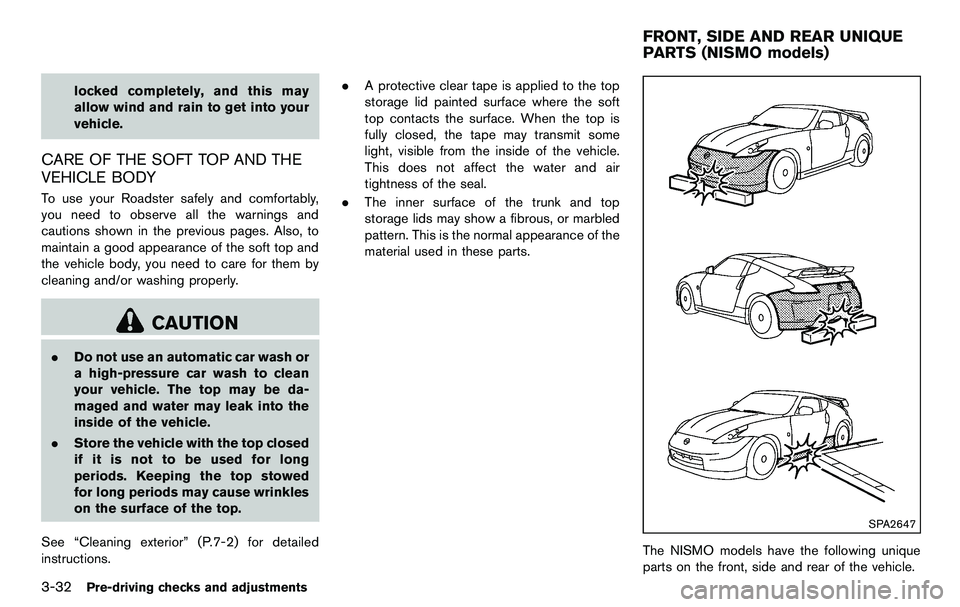
SPA2647
The NISMO models have the following unique
parts on the front, side and rear of the vehicle.
FRONT, SIDE AND REAR UNIQUE
PARTS (NISMO models)
Page 150 of 427
3-34Pre-driving checks and adjustments
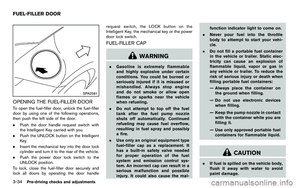
SPA2581
OPENING THE FUEL-FILLER DOOR
To open the fuel-filler door, unlock the fuel-filler
door by using one of the following operations,
then push the left side of the door.
.Push the door handle request switch with
the Intelligent Key carried with you.
. Push the UNLOCK button on the Intelligent
Key.
. Insert the mechanical key into the door lock
cylinder and turn it to the rear of the vehicle.
. Push the power door lock switch to the
UNLOCK position.
To lock, close the fuel-filler door securely and
lock all doors by operating the door handle request switch, the LOCK button on the
Intelligent Key, the mechanical key or the power
door lock switch.
FUEL-FILLER CAP
WARNING
.
Gasoline is extremely flammable
and highly explosive under certain
conditions. You could be burned or
seriously injured if it is misused or
mishandled. Always stop engine
and do not smoke or allow open
flames or sparks near the vehicle
when refueling.
. Do not attempt to top off the fuel
tank after the fuel pump nozzle
shuts off automatically. Continued
refueling may cause fuel overflow,
resulting in fuel spray and possibly
a fire.
. Use only an original equipment type
fuel-filler cap as a replacement. It
has a built-in safety valve needed
for proper operation of the fuel
system and emission control sys-
tem. An incorrect cap can result in a
serious malfunction and possible
injury. It could also cause the mal- function indicator light to come on.
. Never pour fuel into the throttle
body to attempt to start your vehi-
cle.
. Do not fill a portable fuel container
in the vehicle or trailer. Static elec-
tricity can cause an explosion of
flammable liquid, vapor or gas in
any vehicle or trailer. To reduce the
risk of serious injury or death when
filling portable fuel containers:
— Always place the container on
the ground when filling.
— Do not use electronic devices when filling.
— Keep the pump nozzle in contact with the container while you are
filling it.
— Use only approved portable fuel containers for flammable liquid.
CAUTION
. If fuel is spilled on the vehicle body,
flush it away with water to avoid
paint damage.
FUEL-FILLER DOOR
Page 151 of 427
.Insert the cap straight into the fuel-
filler tube, then tighten until the
fuel-filler cap clicks. Failure to tight-
en the fuel-filler cap properly may
cause the
malfunction indicator
light (MIL) to illuminate. If the
light illuminates because the fuel-
filler cap is loose or missing, tighten
or install the cap and continue to
drive the vehicle. The
light
should turn off after a few driving
trips. If the
light does not turn
off after a few driving trips, have the
vehicle inspected by a NISSAN deal-
er.
. The LOOSE FUEL CAP warning will
appear if the fuel-filler cap is not
properly tightened. It may take a few
driving trips for the message to be
displayed. Failure to tighten the
fuel-filler cap properly after the
LOOSE FUEL CAP warning appears
may cause the
Malfunction
Indicator Light (MIL) to illuminate.
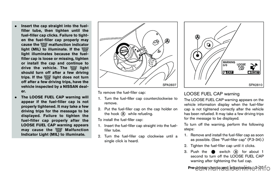
SPA2837
To remove the fuel-filler cap:
1. Turn the fuel-filler cap counterclockwise to remove.
2. Put the fuel-filler cap on the cap holder on the hook
*Awhile refueling.
To install the fuel-filler cap:
1. Insert the fuel-filler cap straight into the fuel- filler tube.
2. Turn the fuel-filler cap clockwise until a single click is heard.
SPA2810
LOOSE FUEL CAP warning
The LOOSE FUEL CAP warning appears on the
vehicle information display when the fuel-filler
cap is not tightened correctly after the vehicle
has been refueled. It may take a few driving trips
for the message to be displayed.
To turn off the warning, perform the following
steps:
1. Remove and install the fuel-filler cap as soonas possible. (See “Fuel-filler cap” (P.3-34) .)
2. Tighten the fuel-filler cap until it clicks.
3. Push the
switch*Afor about 1
second to turn off the LOOSE FUEL CAP
warning after tightening the fuel cap.
Pre-driving checks and adjustments3-35
Page 153 of 427

SPA2447
INSIDE MIRROR
Adjust the height and the angle of the inside
mirror to the desired position.
SPA2143
Manual anti-glare type
The night position*1will reduce glare from the
headlights of vehicles behind you at night.
Use the day position
*2when driving in daylight
hours.
WARNING
Use the night position only when ne-
cessary, because it reduces rear view
clarity.
SPA2450
Automatic anti-glare type
The inside mirror is designed so that it
automatically changes reflection according to
the intensity of the headlights of the following
vehicle.
The anti-glare system will be automatically
turned on when the ignition switch is pushed
to the ON position.
When the anti-glare system is turned on, the
indicator light
*Awill illuminate and excessive
glare from the headlights of the vehicle behind
you will be reduced.
Push the “*” switch
*Cto make the inside
rearview mirror operate normally. The indicator
Pre-driving checks and adjustments3-37
MIRRORS
Page 154 of 427

3-38Pre-driving checks and adjustments
light will turn off. Push the “I” switch*Dto turn
the system on.
Do not allow any object to cover the
sensors
*Eor apply glass cleaner on
them. Doing so will reduce the sensitivity
of the sensor, resulting in improper opera-
tion.
For the HomeLink
®Universal Transceiver opera-
tion, see “HomeLink®Universal Transceiver”
(P.2-49) .
OUTSIDE MIRRORS
WARNING
Objects viewed in the outside mirror on
the passenger side are closer than they
appear. Be careful when moving to the
right. Using only this mirror could cause
an accident. Use the inside mirror or
glance over your shoulder to properly
judge distances to other objects.
SPA2319
Adjusting outside mirrors
The outside mirror control switch is located on
the armrest.
The outside mirror will operate only when the
ignition switch is in the ACC or ON position.
Turn the switch right or left to select the right or
left side mirror
*1, then adjust using the control
switch
*2.
Defrosting outside mirrors
The outside mirrors will be heated when the rear
window defroster switch is operated.
Page 175 of 427

Predicted course lines*6:
Indicate the predicted course when backing up.
The predicted course lines will be displayed on
the monitor when the selector/shift lever is in the
R (Reverse) position and the steering wheel is
turned. The predicted course lines will move
depending on how much the steering wheel is
turned and will not be displayed while the
steering wheel is in the neutral position.
HOW TO PARK WITH PREDICTED
COURSE LINES
WARNING
. Always turn and check that it is safe
to park your car before backing up.
Always back up slowly.
. Use the displayed lines as a refer-
ence. The lines are highly affected
by the number of occupants, fuel
level, vehicle position, road condi-
tion and road grade.
. If the tires are replaced with differ-
ent sized tires, the predicted course
line may not be displayed correctly.
. On a snow-covered or slippery road,
there may be a difference between
the predicted course line and the actual course line.
. If predicted course lines are dis-
played incorrectly, drive the vehicle
on a straight road for 110 yd (100 m)
at a speed of above 20 MPH (30
km/h) .
. The displayed lines will appear
slightly off to the right because the
rearview camera is not installed in
the rear center of the vehicle.
. The distance guide line and the
vehicle width guide line should be
used as a reference only when the
vehicle is on a level paved surface.
The distance viewed on the monitor
is for reference only and may be
different than the actual distance
between the vehicle and displayed
objects.
. When backing up the vehicle up a
hill, objects viewed in the monitor
are further than they appear. When
backing up the vehicle down a hill,
objects viewed in the monitor are
closer than they appear. Use the
inside mirror or glance over your
shoulder to properly judge dis-
tances to other objects. The vehicle width and predicted course
lines are wider than the actual width and
course.
Center display, heater, air conditioner, audio, phone and voice recognition systems4-19
Page 288 of 427
5-4Starting and driving
pressure telltale.
Your vehicle has also been equipped with a
TPMS malfunction indicator to indicate when the
system is not operating properly. The TPMS
malfunction indicator is combined with the low
tire pressure telltale. When the system detects a
malfunction, the telltale will flash for approxi-
mately one minute and then remain continuously
illuminated. This sequence will continue upon
subsequent vehicle start-ups as long as the
malfunction exists. When the malfunction indi-
cator is illuminated, the system may not be able
to detect or signal low tire pressure as intended.
TPMS malfunctions may occur for a variety of
reasons, including the installation of replace-
ment or alternate tires or wheels on the vehicle
that prevent the TPMS from functioning properly.
Always check the TPMS malfunction telltale
after replacing one or more tires or wheels on
your vehicle to ensure that the replacement or
alternate tires and wheels allow the TPMS to
continue to function properly.
Additional information
.The TPMS does not monitor the tire
pressure of the spare tire.
. The TPMS will activate only when the
vehicle is driven at speeds above 16 MPH
(25 km/h) . Also, this system may not detect
a sudden drop in tire pressure (for example a flat tire while driving) .
. The low tire pressure warning light does not
automatically turn off when the tire pressure
is adjusted. After the tire is inflated to the
recommended pressure, the vehicle must be
driven at speeds above 16 MPH (25 km/h)
to activate the TPMS and turn off the low tire
pressure warning light. Use a tire pressure
gauge to check the tire pressure.
. Tire pressure rises and falls depending on
the heat caused by the vehicle’s operation
and the outside temperature. Low outside
temperature can lower the temperature of
the air inside the tire which can cause a
lower tire inflation pressure. This may cause
the low tire pressure warning light to
illuminate. If the warning light illuminates in
low ambient temperature, check the tire
pressure for all four tires.
For additional information, see “Low tire pres-
sure warning light” (P.2-12) and “Tire Pressure
Monitoring System (TPMS)” (P.6-2) .WARNING
. If the low tire pressure warning light
illuminates while driving, avoid sud-
den steering maneuvers or abrupt
braking, reduce vehicle speed, pull off the road to a safe location and
stop the vehicle as soon as possi-
ble. Driving with under-inflated tires
may permanently damage the tires
and increase the likelihood of tire
failure. Serious vehicle damage
could occur and may lead to an
accident and could result in serious
personal injury. Check the tire pres-
sure for all four tires. Adjust the tire
pressure to the recommended COLD
tire pressure shown on the Tire and
Loading Information label to turn
the low tire pressure warning light
OFF. If the light still illuminates
while driving after adjusting the tire
pressure, a tire may be flat. If you
have a flat tire, replace it with a
spare tire as soon as possible. (See
“Flat tire” (P.6-2) for changing a flat
tire.)
. When a spare tire is mounted or a
wheel is replaced, the TPMS will not
function and the low tire pressure
warning light will flash for approxi-
mately 1 minute. The light will
remain on after 1 minute. Contact
your NISSAN dealer as soon as
possible for tire replacement and/
or system resetting.
Page 289 of 427
.Replacing tires with those not ori-
ginally specified by NISSAN could
affect the proper operation of the
TPMS.
. Do not inject any tire liquid or
aerosol tire sealant into the tires,
as this may cause a malfunction of
the tire pressure sensors (for mod-
els not equipped with the emer-
gency tire puncture repair kit) .
. If you used the Emergency Tire
Sealant to repair a minor tire punc-
ture, your NISSAN dealer will also
need to replace the TPMS sensor in
addition to repairing or replacing
the tire (for models equipped with
the emergency tire puncture repair
kit) .
. NISSAN recommends using only
NISSAN Genuine Emergency Tire
Sealant provided with your vehicle.
Other tire sealants may damage the
valve stem seal which can cause the
tire to lose air pressure (for models
equipped with the emergency tire
puncture repair kit) .CAUTION
.The TPMS may not function properly
when the wheels are equipped with
tire chains or the wheels are buried
in snow.
. Do not place metalized film or any
metal parts (antenna, etc.) on the
windows. This may cause poor re-
ception of the signals from the tire
pressure sensors, and the TPMS will
not function properly.
Some devices and transmitters may temporarily
interfere with the operation of the TPMS and
cause the low tire pressure warning light to
illuminate. Some examples are:
. Facilities or electric devices using similar
radio frequencies are near the vehicle.
. If a transmitter set to similar frequencies is
being used in or near the vehicle.
. If a computer (or similar equipment) or a DC/
AC converter is being used in or near the
vehicle. FCC Notice:
For USA:
This device complies with Part 15 of the
FCC Rules. Operation is subject to the
following two conditions:
(1) This device may not cause harmful
interference, and (2) this device must
accept any interference received, including
interference that may cause undesired
operation.
Note: Changes or modifications not ex-
pressly approved by the party responsible
for compliance could void the user’s
authority to operate the equipment.
For Canada:
This device complies with RSS-210 of
Industry Canada. Operation is subject to
the following two conditions:
(1) this device may not cause interference,
and (2) this device must accept any inter-
ference, including interference that may
cause undesired operation of the device.
Starting and driving5-5