2012 NISSAN 370Z COUPE battery
[x] Cancel search: batteryPage 100 of 427
2-36Instruments and controls
.Turn signals do not work when the
hazard warning flasher lights are
on.
The flasher can be actuated with the ignition
switch in any position.
Some state laws may prohibit the use of
the hazard warning flasher switch while
driving.
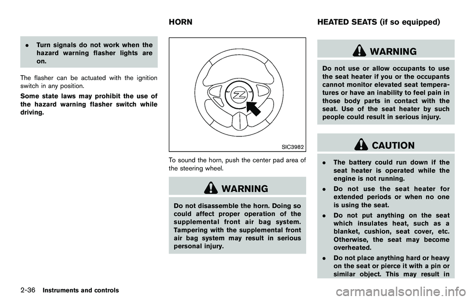
SIC3982
To sound the horn, push the center pad area of
the steering wheel.
WARNING
Do not disassemble the horn. Doing so
could affect proper operation of the
supplemental front air bag system.
Tampering with the supplemental front
air bag system may result in serious
personal injury.
WARNING
Do not use or allow occupants to use
the seat heater if you or the occupants
cannot monitor elevated seat tempera-
tures or have an inability to feel pain in
those body parts in contact with the
seat. Use of the seat heater by such
people could result in serious injury.
CAUTION
. The battery could run down if the
seat heater is operated while the
engine is not running.
. Do not use the seat heater for
extended periods or when no one
is using the seat.
. Do not put anything on the seat
which insulates heat, such as a
blanket, cushion, seat cover, etc.
Otherwise, the seat may become
overheated.
. Do not place anything hard or heavy
on the seat or pierce it with a pin or
similar object. This may result in
HORN HEATED SEATS (if so equipped)
Page 102 of 427
2-38Instruments and controls
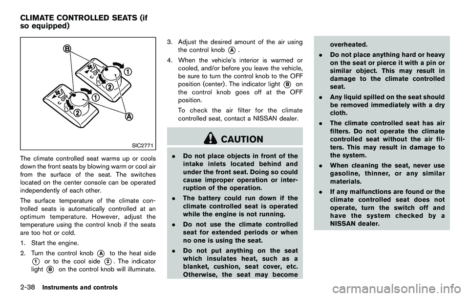
SIC2771
The climate controlled seat warms up or cools
down the front seats by blowing warm or cool air
from the surface of the seat. The switches
located on the center console can be operated
independently of each other.
The surface temperature of the climate con-
trolled seats is automatically controlled at an
optimum temperature. However, adjust the
temperature using the control knob if the seats
are too hot or cold.
1. Start the engine.
2. Turn the control knob
*Ato the heat side
*1or to the cool side*2. The indicator
light
*Bon the control knob will illuminate. 3. Adjust the desired amount of the air using
the control knob
*A.
4. When the vehicle’s interior is warmed or cooled, and/or before you leave the vehicle,
be sure to turn the control knob to the OFF
position (center) . The indicator light
*Bon
the control knob goes off at the OFF
position.
To check the air filter for the climate
controlled seat, contact a NISSAN dealer.
CAUTION
. Do not place objects in front of the
intake inlets located behind and
under the front seat. Doing so could
cause improper operation or inter-
ruption of the operation.
. The battery could run down if the
climate controlled seat is operated
while the engine is not running.
. Do not use the climate controlled
seat for extended periods or when
no one is using the seat.
. Do not put anything on the seat
which insulates heat, such as a
blanket, cushion, seat cover, etc.
Otherwise, the seat may become overheated.
. Do not place anything hard or heavy
on the seat or pierce it with a pin or
similar object. This may result in
damage to the climate controlled
seat.
. Any liquid spilled on the seat should
be removed immediately with a dry
cloth.
. The climate controlled seat has air
filters. Do not operate the climate
controlled seat without the air fil-
ters. This may result in damage to
the system.
. When cleaning the seat, never use
gasoline, thinner, or any similar
materials.
. If any malfunctions are found or the
climate controlled seat does not
operate, turn the switch off and
have the system checked by a
NISSAN dealer.
CLIMATE CONTROLLED SEATS (if
so equipped)
Page 103 of 427
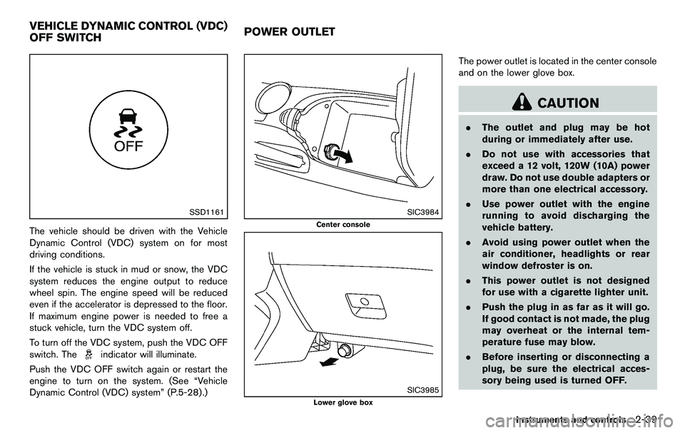
SSD1161
The vehicle should be driven with the Vehicle
Dynamic Control (VDC) system on for most
driving conditions.
If the vehicle is stuck in mud or snow, the VDC
system reduces the engine output to reduce
wheel spin. The engine speed will be reduced
even if the accelerator is depressed to the floor.
If maximum engine power is needed to free a
stuck vehicle, turn the VDC system off.
To turn off the VDC system, push the VDC OFF
switch. The
indicator will illuminate.
Push the VDC OFF switch again or restart the
engine to turn on the system. (See “Vehicle
Dynamic Control (VDC) system” (P.5-28) .)
SIC3984
Center console
SIC3985
Lower glove box
The power outlet is located in the center console
and on the lower glove box.
CAUTION
. The outlet and plug may be hot
during or immediately after use.
. Do not use with accessories that
exceed a 12 volt, 120W (10A) power
draw. Do not use double adapters or
more than one electrical accessory.
. Use power outlet with the engine
running to avoid discharging the
vehicle battery.
. Avoid using power outlet when the
air conditioner, headlights or rear
window defroster is on.
. This power outlet is not designed
for use with a cigarette lighter unit.
. Push the plug in as far as it will go.
If good contact is not made, the plug
may overheat or the internal tem-
perature fuse may blow.
. Before inserting or disconnecting a
plug, be sure the electrical acces-
sory being used is turned OFF.
Instruments and controls2-39
VEHICLE DYNAMIC CONTROL (VDC)
OFF SWITCH POWER OUTLET
Page 110 of 427
2-46Instruments and controls
Automatic window lowering (Roadster
models)
When the soft top operating switch is pressed,
the power windows will automatically be low-
ered completely. The windows do not rise
automatically after the soft top open/close
operation is completed. Use the power window
switches to raise them.
Automatic adjusting function
CAUTION
When the battery cable is removed from
the battery terminal, do not close either
of the front doors. The automatic win-
dow adjusting function will not work
and the side roof panel may be da-
maged.
The power window has an automatic adjusting
function. When the door is being opened, the
window is automatically lowered slightly to avoid
contact between the window and the side roof
panel. When the door is closed, the window is
automatically raised slightly.
While the automatic adjusting function does not
work, the window will be controlled as follows: .
When the door is opened, the window
lowers for approximately 2 seconds.
. While the door is open, the window cannot
be raised.
If the windows do not close automatically
If the power window automatic function (closing
only) does not operate properly, perform the
following procedure to initialize the power
window system.
1. Push the ignition switch to the ON position.
2. Close the door and soft top (Roadster
models) .
3. Open the window completely by operating the power window switch.
4. Pull the power window switch and hold it to close the window, and then hold the switch
more than 3 seconds after the window is
closed completely.
5. Release the power window switch. Operate the window by the automatic function to
confirm the initialization is complete.
6. Perform steps 2 through 5 above for other windows.
If the power window automatic function does
not operate properly after performing the pro-
cedure above, have your vehicle checked by a
NISSAN dealer.
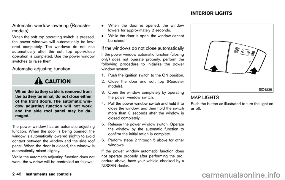
SIC4238
MAP LIGHTS
Push the button as illustrated to turn the light on
or off.
INTERIOR LIGHTS
Page 111 of 427
SIC4239
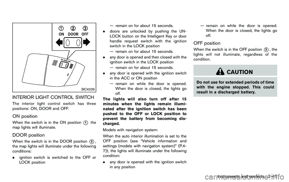
INTERIOR LIGHT CONTROL SWITCH
The interior light control switch has three
positions: ON, DOOR and OFF.
ON position
When the switch is in the ON position*1the
map lights will illuminate.
DOOR position
When the switch is in the DOOR position*2,
the map lights will illuminate under the following
conditions:
. ignition switch is switched to the OFF or
LOCK position — remain on for about 15 seconds.
. doors are unlocked by pushing the UN-
LOCK button on the Intelligent Key or door
handle request switch with the ignition
switch in the LOCK position
— remain on for about 15 seconds.
. any door is opened and then closed with the
ignition switch in the LOCK position
— remain on for about 15 seconds.
. any door is opened with the ignition switch
in the ACC or ON position
— remain on while the door is opened.
When the door is closed, the lights go
off.
The lights will also turn off after 15
minutes when the lights remain illumi-
nated after the ignition switch has been
pushed to the OFF or LOCK position to
prevent the battery from becoming dis-
charged.
Models with navigation system:
When the auto interior illumination is set to the
OFF position (see “Vehicle information and
settings (models with navigation system)” (P.4-
7)), the lights will illuminate under the following
condition:
. any door is opened with the ignition switch
in any position — remain on while the door is opened.
When the door is closed, the lights go
off.
OFF position
When the switch is in the OFF position*3, the
lights will not illuminate, regardless of the
condition.
CAUTION
Do not use for extended periods of time
with the engine stopped. This could
result in a discharged battery.
Instruments and controls2-47
Page 112 of 427
2-48Instruments and controls
SIC3869
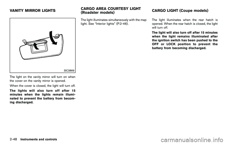
The light on the vanity mirror will turn on when
the cover on the vanity mirror is opened.
When the cover is closed, the light will turn off.
The lights will also turn off after 15
minutes when the lights remain illumi-
nated to prevent the battery from becom-
ing discharged.The light illuminates simultaneously with the map
light. See “Interior lights” (P.2-46).
The light illuminates when the rear hatch is
opened. When the rear hatch is closed, the light
will turn off.
The light will also turn off after 15 minutes
when the light remains illuminated after
the ignition switch has been pushed to the
OFF or LOCK position to prevent the
battery from becoming discharged.
VANITY MIRROR LIGHTS
CARGO AREA COURTESY LIGHT
(Roadster models)CARGO LIGHT (Coupe models)
Page 113 of 427
The light illuminates when the trunk lid is
opened. When the trunk lid is closed, the light
turns off.HomeLink®Universal Transceiver provides a
convenient way to consolidate the functions of
up to three individual hand-held transmitters into
one built-in device.
HomeLink
®Universal Transceiver:
. Will operate most Radio Frequency (RF)
devices such as garage doors, gates, home
and office lighting, entry door locks and
security systems.
. Is powered by your vehicle’s battery. No
separate batteries are required. If the
vehicle’s battery is discharged or is dis-
connected, HomeLink
®will retain all pro-
gramming.
Once HomeLink
®Universal Transceiver is
programmed, retain the original transmit-
ter for future programming procedures
(Example: new vehicle purchases) . Upon
sale of the vehicle, the programmed
HomeLink
®Universal Transceiver buttons
should be erased for security purposes.
For additional information, see “Program-
ming HomeLink
®” (P.2-50) .
WARNING
. Do not use HomeLink®Universal
Transceiver with any garage door
opener that lacks safety stop and reverse features as required by
federal safety standards. (These
standards became effective for
opener models manufactured after
April 1, 1982.) A garage door opener
which cannot detect an object in the
path of a closing garage door and
then automatically stop and reverse,
does not meet current federal safety
standards. Using a garage door
opener without these features in-
creases the risk of serious injury or
death.
. During programming procedure,
your garage door or security gate
may open or close. Make sure that
people and objects are clear of the
garage door, gate, etc. that you are
programming.
. Your vehicle’s engine should be
turned off while programming
HomeLink
®Universal Transceiver.
Instruments and controls2-49
TRUNK LIGHT (Roadster models) HomeLink®UNIVERSAL
TRANSCEIVER (if so equipped)
Page 115 of 427
button - releasing when the device begins to
activate.
5. If the indicator light on HomeLink
®blinks
rapidly for two seconds and then turns solid,
HomeLink
®has picked up a “rolling code”
garage door opener signal. You will need to
proceed with the next steps to train
HomeLink
®, completing the programming
may require a ladder and another person
for convenience.
6. Push and release the program button located on the garage door opener’s motor
to activate the “training mode”. This button is
usually located near the antenna wire that
hangs down from the motor. If the wire
originates from under a light lens, you will
need to remove the lens to access the
training button.
NOTE:
Once you have pushed and released
the training button on the garage door
opener’s motor and the “training light”
is lit, you have 30 seconds in which to
perform step 7. For convenience, use
the help of a second person to assist
when performing this step.
7. Quickly (within 30 seconds of pushing and releasing the garage door opener training
button) and firmly push and release the HomeLink
®button you have just pro-
grammed. Push and release the HomeLink®
button up to three times to complete the
training.
8. Your HomeLink
®button should now be
programmed. To program the remaining
HomeLink
®buttons for additional door or
gate openers, follow steps 2 through 8 only.
NOTE:
Do not repeat step 1 unless you want to
“clear” all previously programmed
HomeLink
®buttons.
If you have any questions or are having difficulty
programming your HomeLink
®buttons, please
refer to the HomeLink®web site at: www.
homelink.com or call 1-800-355-3515.
PROGRAMMING HomeLink®FOR CA-
NADIAN CUSTOMERS
Prior to 1992, D.O.C. regulations required
hand-held transmitters to stop transmitting after
2 seconds. To program your hand-held trans-
mitter to HomeLink
®, continue to push and hold
the HomeLink®button (note steps 2 through 4
under “Programming HomeLink®”) while you
push and re-push (“cycle”) your hand-held
transmitter every 2 seconds until the indicator
light flashes rapidly (indicating successful pro-
gramming) . NOTE:
If programming a garage door opener, etc.,
it is advised to unplug the device during
the “cycling” process to prevent possible
damage to the garage door opener com-
ponents.
OPERATING THE HomeLink®UNIVER-
SAL TRANSCEIVER
HomeLink®Universal Transceiver (once pro-
grammed) may now be used to activate the
garage door, etc. To operate, simply push the
appropriate programmed HomeLink
®Universal
Transceiver button. The red indicator light will
illuminate while the signal is being transmitted.
PROGRAMMING TROUBLE-DIAGNO-
SIS
If HomeLink®does not quickly learn the hand-
held transmitter information:
. replace the hand-held transmitter batteries
with new batteries.
. position the hand-held transmitter with its
battery area facing away from the
HomeLink
®surface.
. push and hold both the HomeLink®and
hand-held transmitter buttons without inter-
ruption.
. position the hand-held transmitter 2 to 5 in
(50 to 127 mm) away from the HomeLink
®
Instruments and controls2-51